|
|
Synths |
| Last Updated: | |
| Roland MC-202 Rack (Midi-fied) | |
|
|
|
| MODS 7 - Rackmounting | |
|
| Synth Index
| MC-202 | |
|
| | Case | PSU | IEC | Front | Rear | | |
|
|
Synths |
| Last Updated: | |
| Roland MC-202 Rack (Midi-fied) | |
|
|
|
| MODS 7 - Rackmounting | |
|
| Synth Index
| MC-202 | |
|
| | Case | PSU | IEC | Front | Rear | | |
![]()
|
RACKMOUNTING |
|---|
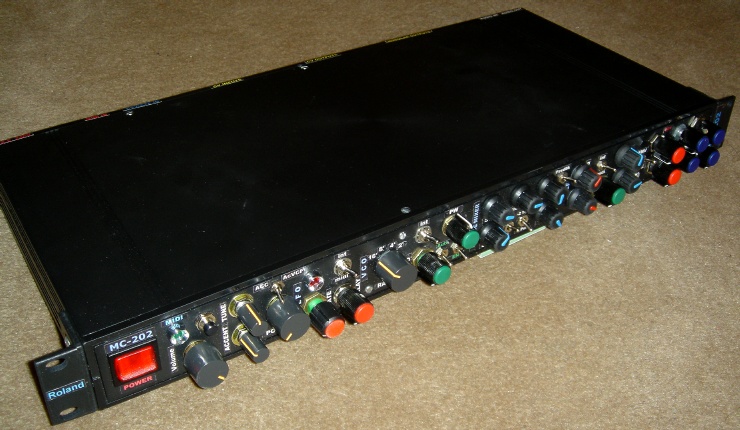
| As I've said before, I intended to rackmount this MC-202 right from the start, so a lot of planning has gone into it. In fact this has become one huge project - it is much harder than i thought, as it involves a lot (I mean LOTS) of wiring / re-wiring. | |||||||||||||||||||||||||||||||||||||||||
| Since it already has the
Modular Upgrade there, it's even harder working on the PCB with all those
flat cable wires attached. It's very easy to make a little mistake and
things would go wrong. Although i did shorten and re-wired most of the
"modular" wires, I actually did these 1st before even removing any sliders
or pots. The sliders/pots are there and easy to re-solder wires to, but the mod wires are not. |
|||||||||||||||||||||||||||||||||||||||||
|
|
|||||||||||||||||||||||||||||||||||||||||
|
|
|||||||||||||||||||||||||||||||||||||||||
| 1. CASE | |||||||||||||||||||||||||||||||||||||||||
| I could have done this in a 2u case, or a large / deep 1u case. But I just don't feel like drilling metal - still after doing the Korg 800DV and MS-20, maybe i still got that drilling phobia, or maybe it's because i got complaints from upstairs while i was drilling the Jen Rack panel.... | |||||||||||||||||||||||||||||||||||||||||
|
So i chose the 1u ABS PLASTIC case again, the same one I did the PAiA Fatman in. |
|||||||||||||||||||||||||||||||||||||||||
|
|
|||||||||||||||||||||||||||||||||||||||||
|
|
|||||||||||||||||||||||||||||||||||||||||
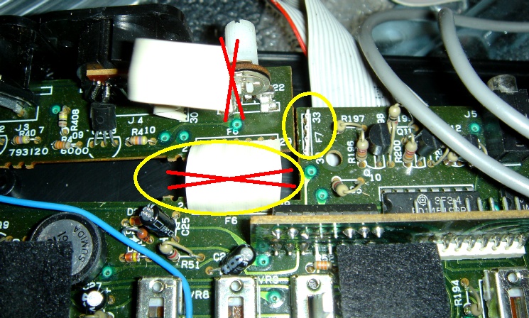
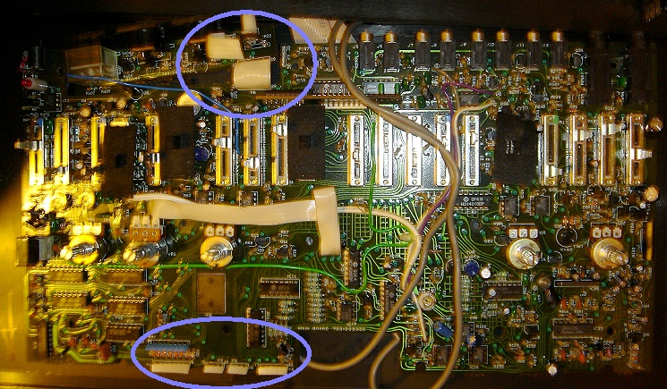
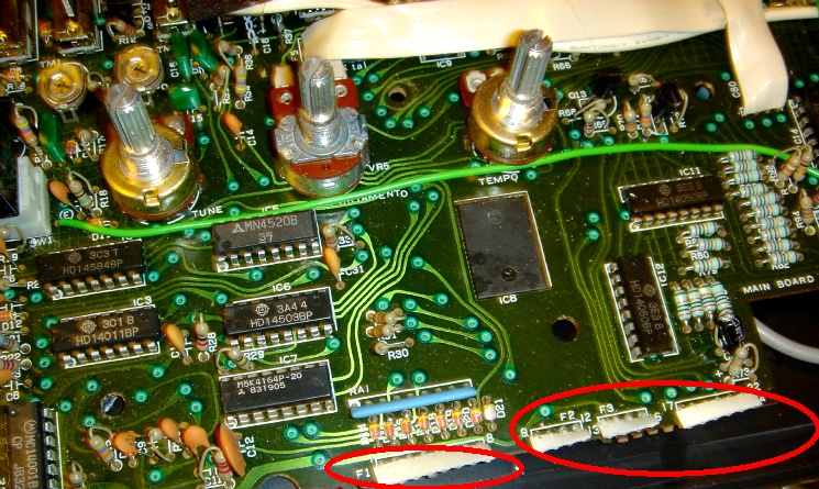
| PCB and Flat-cable Cutting up | |||||||||||||||||||||||||||||||||||||||||
| The actual PCB with the Switchboard and the Sync-board won't fit inside the short 1u i'm using.... so i need to remove them somehow.... | |||||||||||||||||||||||||||||||||||||||||
 |
|||||||||||||||||||||||||||||||||||||||||
| The 1st thing i actually tried, was cutting the internal flat cables that link the main PCB to the Switchboard. Then test the 202 with external CV/Gate to see if it works. As I've expected, the analogue/synth section works without the switchboard. | |||||||||||||||||||||||||||||||||||||||||
 |
|||||||||||||||||||||||||||||||||||||||||
|
Then, looking at the schematics, i find that the Sync-board is probably not needed, although it does have a CAL switch... but it seems that the CAL switch only affects CV that goes thru the internal sequencer. Since the CV IN is already modded to bypass that, so the CAL trimmer is not needed as well, which means the whole Sync-board can be removed. |
|||||||||||||||||||||||||||||||||||||||||
|
|
|||||||||||||||||||||||||||||||||||||||||
| Well, so after that I have an Empty 202 case, Switchboard PCB + Rubber Keys, LCD, and also the Sync-board as spares. I actually sold these on eBay... | |||||||||||||||||||||||||||||||||||||||||
|
Although the MC-202 can be powered by 6x 1.5V batteries or
a 9V DC adapter, I read somewhere that the actual power input can take up
to 17V - 18V. Running it above 15V not only reduces NOISE and also it will
use only around 100mA - 150mA. I also planned to add an internal Midi-CV converter, so i'd need a +/-15V anyway.
A small chassis transformer was used, |
|
||||||||||||||||||||||||||||||||||||||||
|
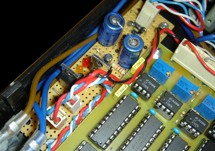
PSU Circuit |
|||||||||||||||||||||||||||||||||||||||||
|
I have the schematics of the Korg MS-02 which has a very
simple PSU circuit, using 7815 and 7915.
So i built a PSU board around this. Funny that when i searched on the web, I found that the ASM-1 PSU board is very similar to this... |
|
||||||||||||||||||||||||||||||||||||||||
|
Disclaimer: I'm not responsible for anything if you try this out and it blows up anything. The circuit / stripboard might contain errors. Also, this is to deal with high voltage electricity, don't bloody electrify yourself!! |
|||||||||||||||||||||||||||||||||||||||||
 |
I don't do custom PCBs, so I do everything in
stripboards/veroboards. This is the same PSU circuit on a 10x30 stripboard. (Click image to enlarge |
||||||||||||||||||||||||||||||||||||||||
| Mounting | |||||||||||||||||||||||||||||||||||||||||
| If i have the 202 PCB on the right, I have enough space on the left for the transformer and the PSU board and the midi interface... | |||||||||||||||||||||||||||||||||||||||||
|
|
|||||||||||||||||||||||||||||||||||||||||
|
|
|||||||||||||||||||||||||||||||||||||||||
|
Well, now that we have the internal PSU, we don't need to
an external power adapter. |
|||||||||||||||||||||||||||||||||||||||||
|
|
|||||||||||||||||||||||||||||||||||||||||
|
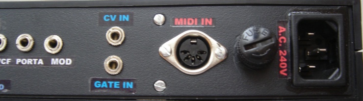
Note: To make the IEC Mains Inlet hole, I use a screwing hand tool, which is an M10 Radius Hand Hole Cutter, 28x21mm (RS Cat.#543-614 or or 541-501), with matching 10A Snap In PCB Mount IEC 320 Plug Socket ( |
|||||||||||||||||||||||||||||||||||||||||
|
|
|||||||||||||||||||||||||||||||||||||||||
|
|
|||||||||||||||||||||||||||||||||||||||||
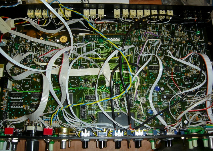
| It took me many nights to do this, taking off all the sliders on the 202 PCB and then re-wiring to the pots on the front panel. | |||||||||||||||||||||||||||||||||||||||||
|
|
|||||||||||||||||||||||||||||||||||||||||
|
Pots: This is a summary of Pots that are needed: |
|||||||||||||||||||||||||||||||||||||||||
|
|||||||||||||||||||||||||||||||||||||||||
|
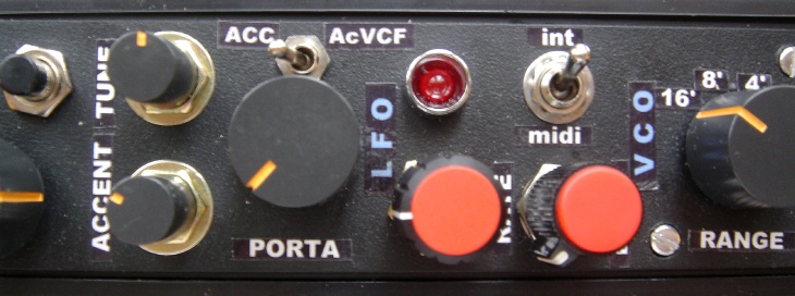
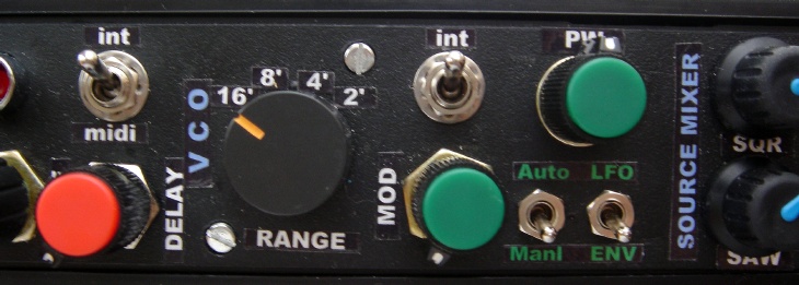
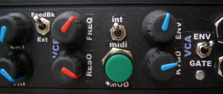
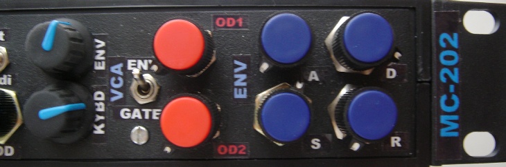
Switches: 1 Toggle Switch for the VCA ENV/GATE, 1 Rotary for the VCO Range Select. Since the 1u is very cramp/tight in space, putting more rotary switches is not a good idea. From the Oakley Moog Rogue Rack, I've learnt one thing - use 2 switches for any 3 position slider switch. So, we can actually use 2 small toggle switches for say the Pulse Width Select, or the Sub-Osc Octave. Further switches are needed for toggle between internal and "Midi Add CV" for the LFO MOD, VCF Cutoff and the Feedback Mod. |
|||||||||||||||||||||||||||||||||||||||||
|
|
|||||||||||||||||||||||||||||||||||||||||
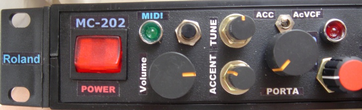
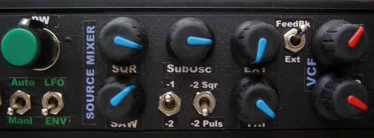
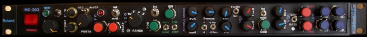
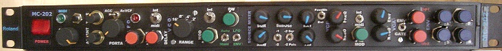
| Front Panel Layout | |||||||||||||||||||||||||||||||||||||||||
 |
|||||||||||||||||||||||||||||||||||||||||
|
The front panel layout is similar to the original MC-202 panel... |
|||||||||||||||||||||||||||||||||||||||||
|
|
|||||||||||||||||||||||||||||||||||||||||
|
Note: |
|||||||||||||||||||||||||||||||||||||||||
|
|
|||||||||||||||||||||||||||||||||||||||||
|
|
|||||||||||||||||||||||||||||||||||||||||
|
|
|||||||||||||||||||||||||||||||||||||||||
|
|
|||||||||||||||||||||||||||||||||||||||||
|
|
|||||||||||||||||||||||||||||||||||||||||
| I actually planned this with Schaeffer's Front Panel Designer. My template is here (fpd file). | |||||||||||||||||||||||||||||||||||||||||
|
|
|||||||||||||||||||||||||||||||||||||||||
| What I've actually done is not exactly as what's on the fpd file, but it's near enough. | |||||||||||||||||||||||||||||||||||||||||
|
|
|||||||||||||||||||||||||||||||||||||||||
| IMPORTANT Wiring NOTE | |||||||||||||||||||||||||||||||||||||||||
|
I actually had a common EARTH wiring between the pots, so
to save me wiring 10 - 20 ground wires from the PCB to the front panel
pots.... However, after that when i power up the 202, it all went funny... it is then i realized one thing.... The GROUNDs on the 202 PCB are not common. They're interlinked via the ground pins of the pots and also the mounting brackets of the pots and the switches! SO: MAKE SURE ALL THE GROUND ON THE PCB ARE ACTUALLY LINKED UP AND CONDUCTING! |
|||||||||||||||||||||||||||||||||||||||||
|
|
|||||||||||||||||||||||||||||||||||||||||
|
|
|||||||||||||||||||||||||||||||||||||||||
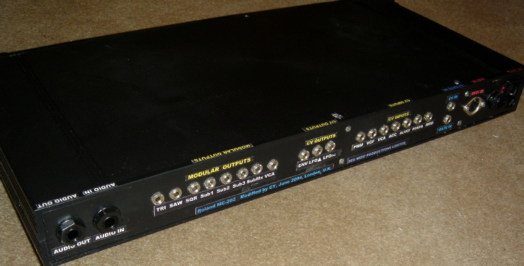
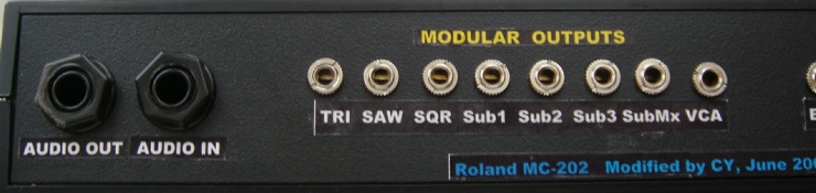
|
Basically, Audio Out and Audio In are 1/4" Jack sockets. I
didn't do a VCA Audio In. The rest, are straight from the modular sockets... |
|||||||||||||||||||||||||||||||||||||||||
|
|
|||||||||||||||||||||||||||||||||||||||||
|
|
|||||||||||||||||||||||||||||||||||||||||
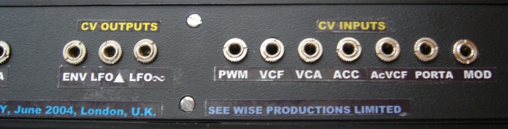
|
Note: For some of the switching sockets, since I don't have the internal sequencer anymore, there's no need for me to wire the CV from the internal to the socket. Instead, I wired the CV Outs / gate Outs from the Midi-CV Interface, so, any thing external that plugs into these socket will still work (and disable the internal midi cv). |
|||||||||||||||||||||||||||||||||||||||||
|
|
|||||||||||||||||||||||||||||||||||||||||
|
|
|||||||||||||||||||||||||||||||||||||||||
| OVERALL RACKMOUNTING COMMENTS: | |||||||||||||||||||||||||||||||||||||||||
|
|||||||||||||||||||||||||||||||||||||||||
|
|
|||||||||||||||||||||||||||||||||||||||||
|
|
|||||||||||||||||||||||||||||||||||||||||
![]()
Next: MODS 8 - MIDI
![]()
![]()
![]()