|
|
Synths |
| Last Updated: | |
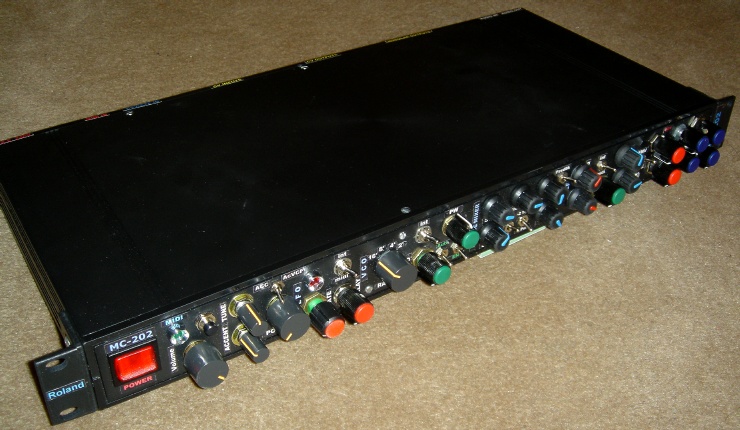
| Roland MC-202 Rack (Midi-fied) | |
|
|
|
| MODS 2 - Sockets - Additional CV In's | |
|
| Synth Index
| MC-202 | |
|
| | VCF CV | PWM CV | VCA CV | MOD CV | | |
|
|
Synths |
| Last Updated: | |
| Roland MC-202 Rack (Midi-fied) | |
|
|
|
| MODS 2 - Sockets - Additional CV In's | |
|
| Synth Index
| MC-202 | |
|
| | VCF CV | PWM CV | VCA CV | MOD CV | | |
![]()
| MOD SOCKETS 2 |
| ADDITIONAL CV INPUTS (VOLTAGE INPUTS) |
| There are quite a few CV inputs that could be added to the MC-202, these include VCF CV IN, PWM CV In and so on. |
|
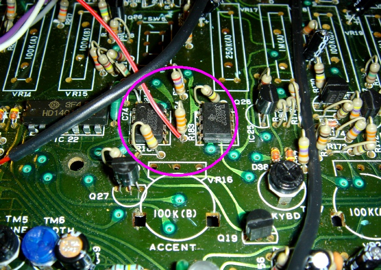
1. VCF CV IN |
| VCF CV In is located at Pin 6 of I.C.24. Wire a socket with a 100k resistor and tap it to this point. |
|
|
| IC24 is located on the middle right of the PCB (facing from TOP/Component side), just under SW5 (ENV/GATE Switch) and the ATTACK (ASDR) Slider, above the ACCENT Pot. |
|
|
 |
| Or you can do it on the other side...facing from the PCB Track side.... |
|
|
| NOTE: There's no need for switched
sockets for the VCF CV input. When a jack is plugged in, the CV is ADDED
to the VCF Cutoff Frequency slider setting. However, if you're wiring these CV In's directly to an internal midi interface or if you'll be constantly having the additional CV jacks plugged in, it is better to have a switch for the CV in. Just a simple SPST to switch the CV IN. |
|
|
|
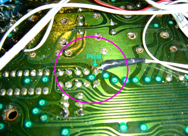
Looking at the Schematics, a PWM CV can be tapped to the centre of the PWM Slider. |
|
|
|
So a socket with a 100k resistor, tapping
to either the PWM Slider or the leg of R191 will provide PWM CV IN. |
|
|
| So, facing from the PCB Track side.... |
|
|
| NOTE: There's no need for switched
sockets for the PWM CV input. When a jack is plugged in, the CV is ADDED
to the PWM Slider setting. However, if you're wiring these CV In's directly to an internal midi interface or if you'll be constantly having the additional CV jacks plugged in, it is better to have a switch for the CV in. Just a simple SPST to switch the CV IN. |
|
|
|
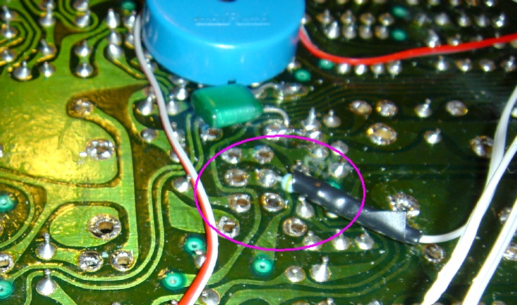
VCA CV IN is actually at the centre of SW5 (VCA ENV/GATE Switch) |
|
|
|
Again, a socket with a 100k resistor
tapping to the middle of SW5 near the BLUE
round internal speaker. |
|
|
| So, facing from the PCB Track side.... |
|
|
| NOTE: The VCA CV In doesn't produce any dramatic effects, it acts like an extra Volume Control, but the width is very limited. |
|
|
|
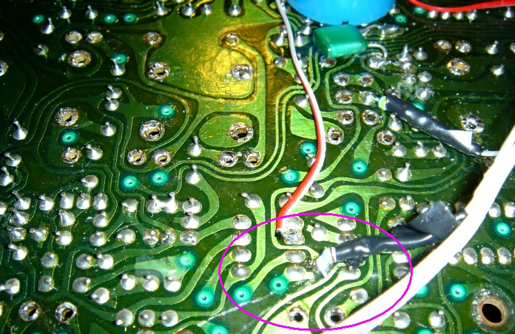
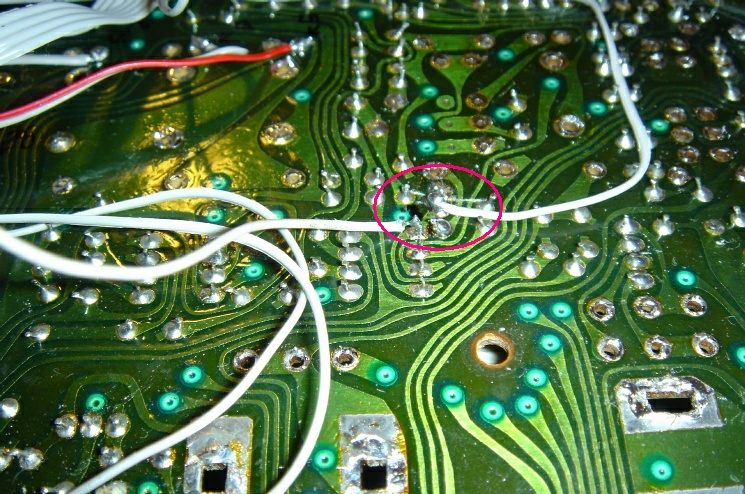
Actual MOD on the MC-202 goes from the LFO Sine output to the MOD Slider. So it is possible to tap a CV IN to the mod... |
|
NOTE: The Analogue Solution Modular Upgrade MOD CV IN is kinda confusing. In fact, whatever was done on this MC-202 wasn't working properly. |
|
|
|
|
|
What the AS Mod CV IN is doing, is actually adding the CV to the Mod Slider, but CUT/Disconnect it from the slider to the LFO Sine Output from IC9. A "Mod Contact" wire linked the Mod Slider back to where it's supposed to be going... |
|
|
|
|
|
It may be easier to actually do a switch to select the MOD from MOD CV IN or LFO Sine Out. |
|
|
|
This way, there's no need to tap to the slider, and just one cut is needed. |
|
|
|
|
|
|
|
On the solder side: |
|
|
![]()
Next: MODS 3 - Additional CV Switches
![]()
![]()
![]()