|
|
Synths |
| Last Updated: | |
| KORG 700S (Mini-Korg K-2) #2 | |
| Includes Step-by-step Proper CV/Gate Mode Installation Guide | |
| | INTRO | MODS | Mod: IEC Mains Socket | Mod: Proper CV/Gate | | |
|
|
Synths |
| Last Updated: | |
| KORG 700S (Mini-Korg K-2) #2 | |
| Includes Step-by-step Proper CV/Gate Mode Installation Guide | |
| | INTRO | MODS | Mod: IEC Mains Socket | Mod: Proper CV/Gate | | |
* My 2nd Korg Mini-Korg 700S... *
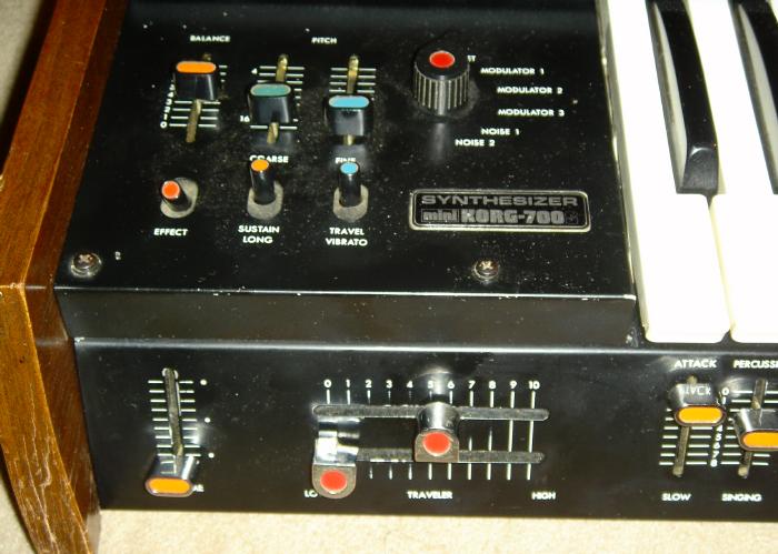
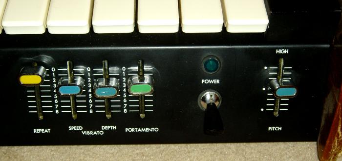
| This second 700S basically has better metal casing cosmetics, but the 2 side wooden panels have a little wear around the edges. Otherwise it's fine, and it's exactly the same as my other 700S. |
|
|
|
|
|
|
 |
![]()
| Mini-Korg 700-S #2 | ||
|---|---|---|
|
||
|
||
|
|
||
|
||
![]()
|
Again, the 700S came with a compartment
which holds a flying lead. |
 |
 |
 |
| Note: To make the IEC Mains Inlet hole, I use a screwing hand tool, which is an M10 Radius Hand Hole Cutter, 28x21mm (RS Cat.#543-614 or or 541-501), with matching 10A Snap In PCB Mount IEC 320 Plug Socket ( |
![]()
| Divided into 4 parts... | |||||||||||||||||||||||||||||||||||||||||||
|
|||||||||||||||||||||||||||||||||||||||||||
|
|||||||||||||||||||||||||||||||||||||||||||
| Part 1: F.A.Q. | |||||||||||||||||||||||||||||||||||||||||||
| Q1: Why "PROPER" CV/Gate? I've got a socket kit.... Q2: Why "PROPER" CV/Gate? Can't I just solder some sockets to the Mini-Korg and give it CV/Gate? |
|||||||||||||||||||||||||||||||||||||||||||
| A1 & A2: Socket Kits or just basic soldering (tapping to the required pads) to give CV/Gate to the 700/700S is possible, but there are some limitations/disadvantages: |
|||||||||||||||||||||||||||||||||||||||||||
|
|||||||||||||||||||||||||||||||||||||||||||
|
|||||||||||||||||||||||||||||||||||||||||||
|
|||||||||||||||||||||||||||||||||||||||||||
| This simple ''Proper Full CV/Gate'' Mod,
will take care of all these, so feeding it External CV/Gate, the Mini-Korg
will respond to it, no need to touch the Mini-Korg keyboard, plus all the
REPEAT / BENDER / PORTAMENTO functions will work with external CV/Gate.
The trimmer lets you ''tune'' the CV, thus putting matching the external CV range to exactly that of the Mini-Korg, so it's also in pitch, in tune with the rest of the outside world. In fact, the external CV/Gate will act exactly like you're playing on the Mini-Korg keyboard. |
|||||||||||||||||||||||||||||||||||||||||||
| Q3: Does the Mini-Korg requires Hz/V or 1V/Oct? Q4: Is it normal +ve Gate, or is it switched (S-Trig) trigger? |
|||||||||||||||||||||||||||||||||||||||||||
| A3: The Mini-Korg requires Hz/V. |
|||||||||||||||||||||||||||||||||||||||||||
| A4: It requires a +ve Gate. For this ''Proper Full CV/Gate'' Mod, any normal > +1V (or > +1.2V) positive gate would work. |
|||||||||||||||||||||||||||||||||||||||||||
| Q5: I have a Korg 700, not a Korg 700S. Are you sure the CV/Gate is the same? Isn't the Korg 700S and enhanced version? Would this CV/Gate mod works with a Korg 700? |
|||||||||||||||||||||||||||||||||||||||||||
| A5: The 700 and 700S differs only that the 700S has an extra PCB and the top left panel. The basic 3 PCBs are identical. So the electronics / PCBs that the CV/Gate deal with are the same. This ''Proper Full CV/Gate'' Mod will work for both the Mini-Korg 700 and Mini-Korg 700S. |
|||||||||||||||||||||||||||||||||||||||||||
|
|||||||||||||||||||||||||||||||||||||||||||
| Part 2: Schematics & Stripboard | |||||||||||||||||||||||||||||||||||||||||||
|
|
The schematics for this ''Proper Full CV/Gate'' Mod
comes from a Japanese website, E-Lab Japan, but since Summer 2004, his
webpage has vanished.
When I first wrote my pages for the 1st 700S, his page was still alive, so I actually linked to his site, since I didn't want "steal" any of his credits and things. But now his site cannot be found.... I have saved his page, in Japanese, mirrored here, with some notes and rough translations. But since I was gonna add CV/Gate to my 2nd Mini-Korg 700S, I decided to take more detailed photos, so I can try showing it step-by-step, it's very similar to his page, but the followings are all in English, with bigger sized photos and additional notes... |
||||||||||||||||||||||||||||||||||||||||||
|
|
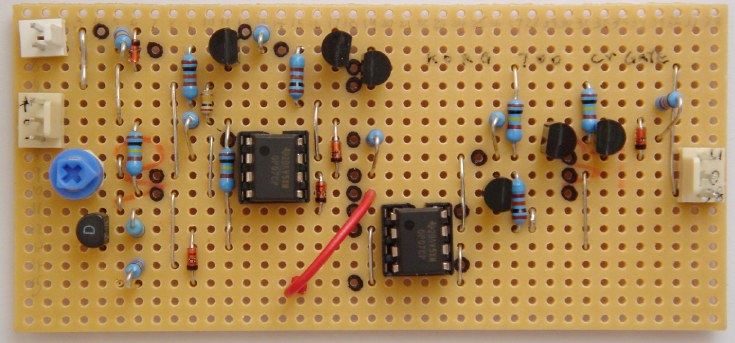
I translated the schematics into a stripboard (or
veroboard).
OP-07 are used because the Mini-Korg uses +20V which is above the usual Op-Amp working voltages. I dun do custom made PCBs, so I convert everything into stripboard. (It's nice, and everyone without PCB making equipment could do it.) |
||||||||||||||||||||||||||||||||||||||||||
| PARTS LIST | |||||||||||||||||||||||||||||||||||||||||||
|
|||||||||||||||||||||||||||||||||||||||||||
|
|
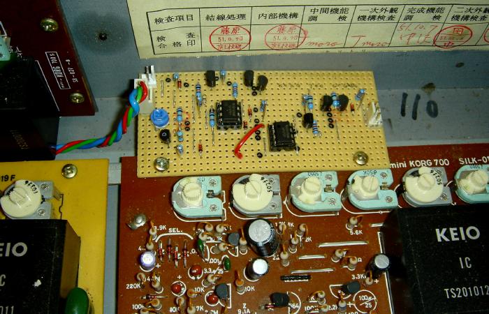
This is roughly how the stripboard looks like when built.
NOTE: |
||||||||||||||||||||||||||||||||||||||||||
|
|
|||||||||||||||||||||||||||||||||||||||||||
| Part 3: Wiring | |||||||||||||||||||||||||||||||||||||||||||
| Open up the Mini-Korg: 1. Removed the Wooden Cheek Sides (unscrew the 3 screws one each side) 2. Remove the Top Covering Panel (2 screws on top left/right, four on the rear) 3. Remove the 2 screws (on the left) that hold the top left panel, so panel can become loose 4. Remove 4 screws (at the bottom of the synth) that hold the keyboard 5. Remove keyboard (altho Keyboard lead (3 wires) still connected... |
|||||||||||||||||||||||||||||||||||||||||||
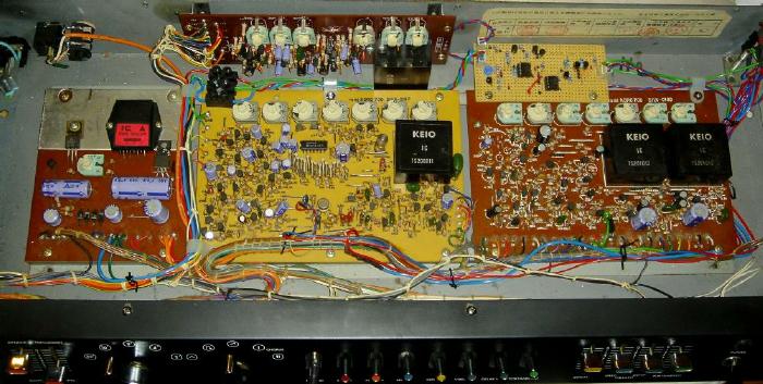
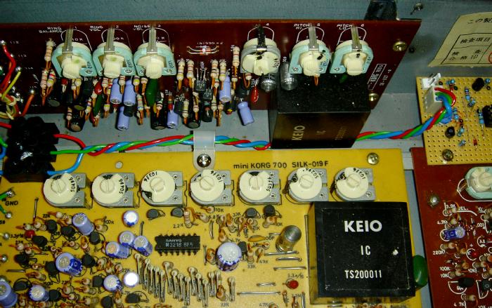
| Then we see the 3 main PCBs. | |||||||||||||||||||||||||||||||||||||||||||
|
|
|||||||||||||||||||||||||||||||||||||||||||
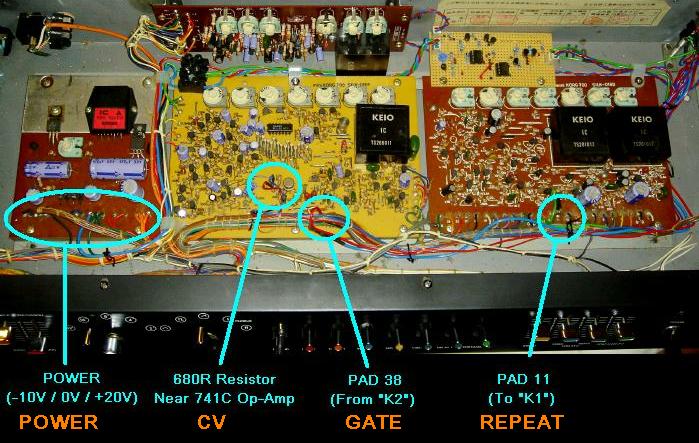
| And the CV/Gate/Repeat Mod Locations are: | |||||||||||||||||||||||||||||||||||||||||||
|
|
|||||||||||||||||||||||||||||||||||||||||||
|
|
|||||||||||||||||||||||||||||||||||||||||||
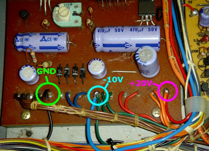
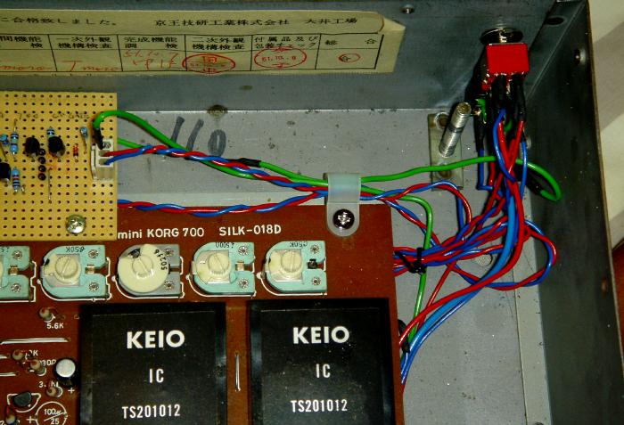
| 1. Power (+20V/0V/-10V) for the stripboard & Stripboard Mounting | |||||||||||||||||||||||||||||||||||||||||||
| Power can be drawn from the Power PSU PCB, which is the PCB on the left. | |||||||||||||||||||||||||||||||||||||||||||
|
|
|||||||||||||||||||||||||||||||||||||||||||
|
These 3 wires will give power to our interface stripboard. I tied them to the bunch of cable nearby, to route them a a space where I can mount eh stripboard: |
|||||||||||||||||||||||||||||||||||||||||||
|
|
|||||||||||||||||||||||||||||||||||||||||||
|
|
|||||||||||||||||||||||||||||||||||||||||||
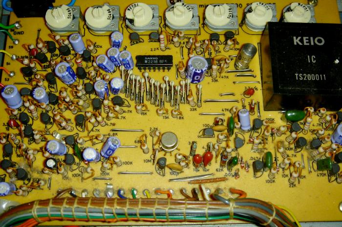
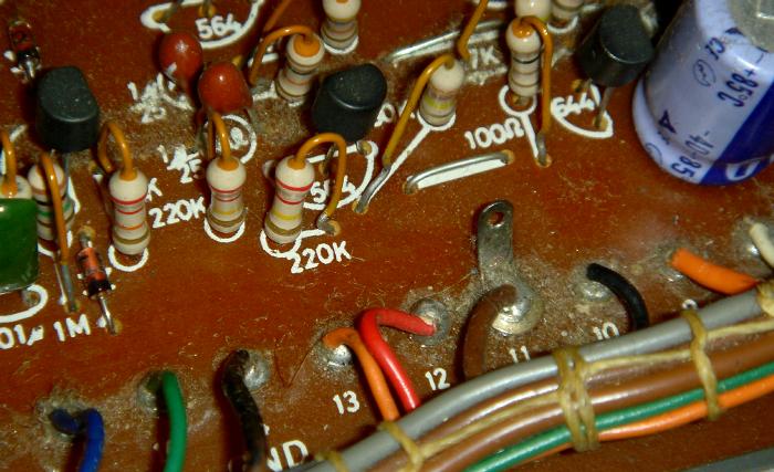
| 2. CV Wiring | |||||||||||||||||||||||||||||||||||||||||||
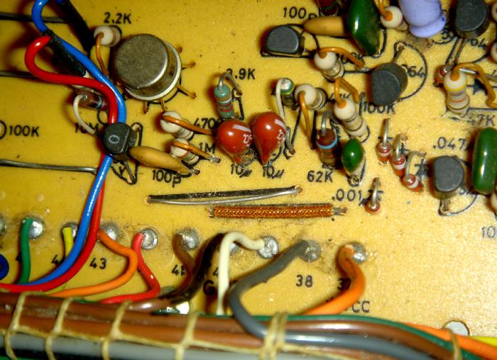
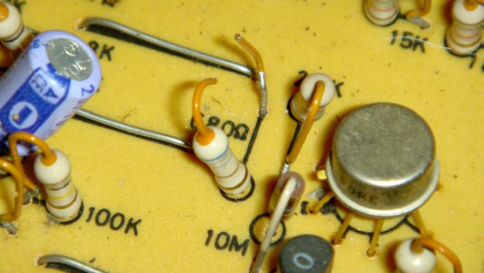
| The CV in is located at the 680R resistor, in the middle PCB, near the round 741C Op-Amp. | |||||||||||||||||||||||||||||||||||||||||||
|
There is a round big transistor look-alike - which is actually an old 741C Op-Amp. The 680R resistor is just left to that. |
|
||||||||||||||||||||||||||||||||||||||||||
| Here you can see clearly, the 680R resistor, just next to the 2.2k and the 10M. |
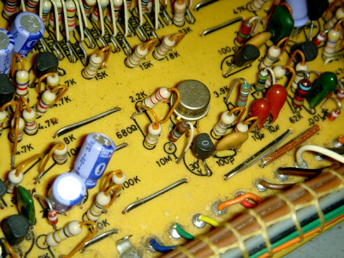 [Click Image to Enlarge] |
||||||||||||||||||||||||||||||||||||||||||
| Another shot, with the 680R resistor circled in red.
C'mon, anyone can see that now!! |
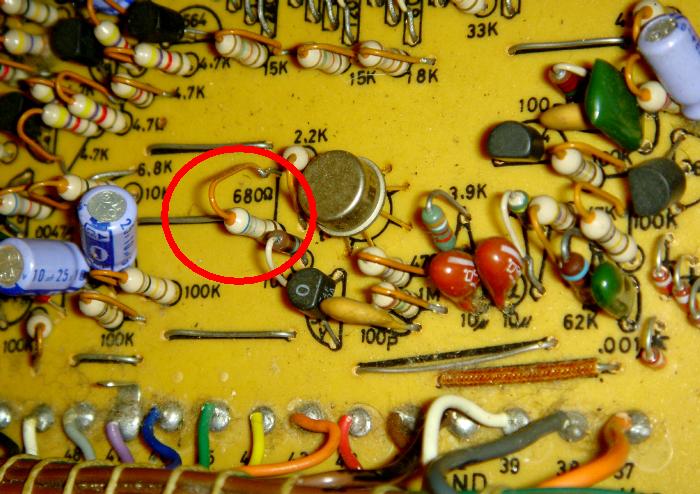 [Click Image to Enlarge] |
||||||||||||||||||||||||||||||||||||||||||
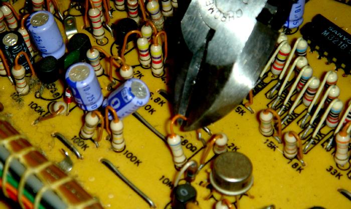
| There is some orange protective paint on the leg of the
680R resistor, since we need to cut this resistor (the loner leg part) and
solder on to each sire, it is easier to scrap off the orange paint before
we cut it.
I used a cutter to scrap off the orange cover, so revealing the metal conductive legs of the resistor. |
 [Click Image to Enlarge] |
||||||||||||||||||||||||||||||||||||||||||
| Then we need to cut this long leg of the 680R resistor.
Cut somewhere higher up, so we have a fair amount on both ends, so we can solder to each end. |
 [Click Image to Enlarge] |
||||||||||||||||||||||||||||||||||||||||||
| Here you see the 680R resistor cut. |
 [Click Image to Enlarge] |
||||||||||||||||||||||||||||||||||||||||||
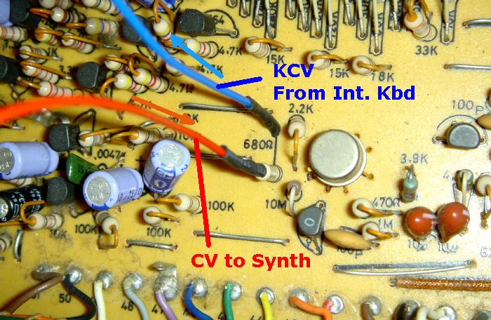
| Two wires are soldered to each cut legs of the 680R
resistor NOTE: The red wire, soldered to 680R resistor, is the CV TO SYNTH. See the next photo. |
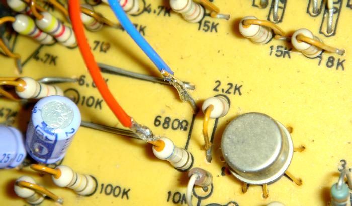 [Click Image to Enlarge] |
||||||||||||||||||||||||||||||||||||||||||
|
|
|||||||||||||||||||||||||||||||||||||||||||
| SWITCH | |||||||||||||||||||||||||||||||||||||||||||
| I used a switch, to switch between Internal Keyboard or
External CV/Gate. (Or you can use sockets with switching connectors) . Wire the RED wire above (the one that is soldered to the 680R) to middle pole of one side of a DPDT switch. The KCV From Int. Kbd (Blue Wire above) goes to one pole on this side of the switch. The remaining pole is connected to the CV Out from the interface stripboard. |
|
||||||||||||||||||||||||||||||||||||||||||
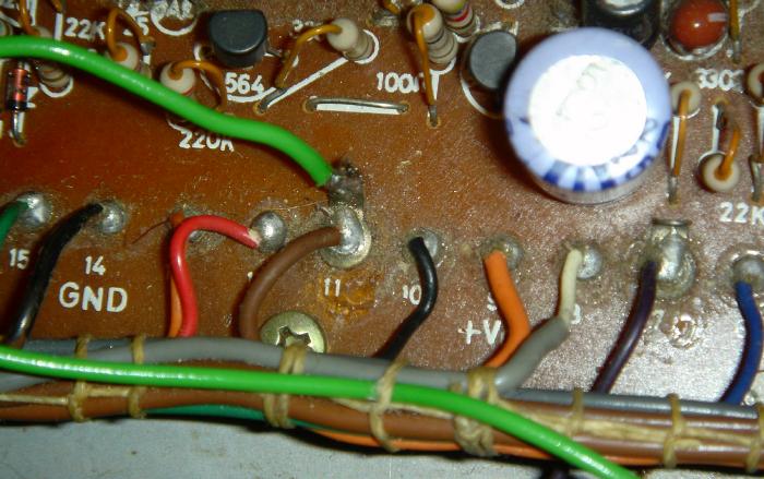
| 3. Gate Wiring | |||||||||||||||||||||||||||||||||||||||||||
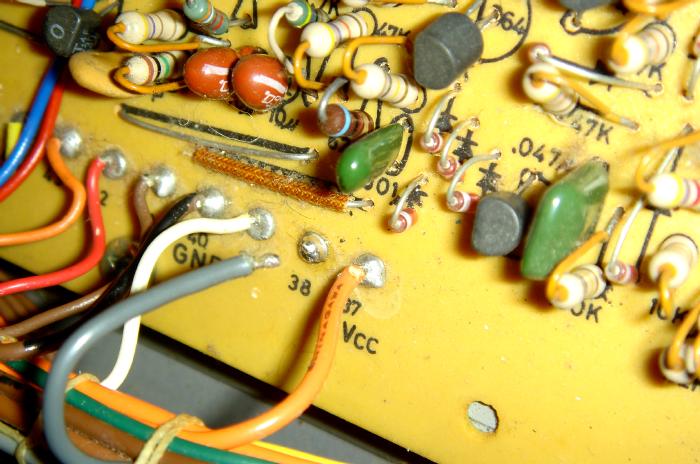
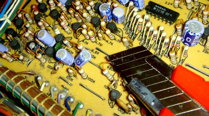
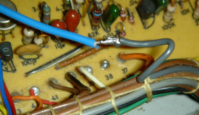
| The Gate is located at Pad 38 in the middle PCB, just a little bit to the right of the 680R resistor we were working on. | |||||||||||||||||||||||||||||||||||||||||||
|
|
|||||||||||||||||||||||||||||||||||||||||||
| De-solder the GREY wire at Pad 38.
|
|
||||||||||||||||||||||||||||||||||||||||||
| The Grey wire is the GATE FROM the Internal Keyboard.
We need to extend this to the switch. |
|
||||||||||||||||||||||||||||||||||||||||||
|
Solder a wire to Pad 38. This wire is the GATE TO SYNTH wire (see next photo). |
|||||||||||||||||||||||||||||||||||||||||||
 |
|||||||||||||||||||||||||||||||||||||||||||
| SWITCH | |||||||||||||||||||||||||||||||||||||||||||
| I used a switch, to switch between Internal Keyboard or
External CV/Gate. (Or you can use sockets with switching connectors) . Wire the RED wire above (the one that is soldered to Pad 38) to middle pole of the other side of a DPDT switch. The Gate From Int. Kbd (GREY Wire above) goes to one pole on this side of the switch. The remaining pole is connected to the Gate Out from the interface stripboard. |
|
||||||||||||||||||||||||||||||||||||||||||
| Well, the CV/gate wiring and switch is
done. The switch now switch between Internal Keyboard, or External CV/Gate. |
|||||||||||||||||||||||||||||||||||||||||||
| 4. "REPEAT" Wiring | |||||||||||||||||||||||||||||||||||||||||||
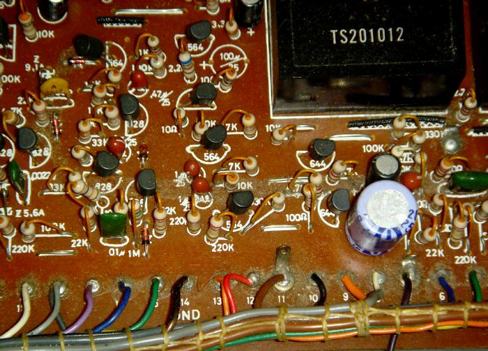
| We need to get the REPEAT/BENDER/PORTAMENTO output from Pad 11, which is located on the PCB on the right. Just solder a wire from Pad 11 to the Interface Stripboard. | |||||||||||||||||||||||||||||||||||||||||||
| Pad 11, located on the PCB board on the right.
|
|
||||||||||||||||||||||||||||||||||||||||||
| Pad 11 is the one with a lag on top.
We can solder to this lag. I scraped the lag a little with a cutter, so that it can stick to the solder properly.
|
|
||||||||||||||||||||||||||||||||||||||||||
|
|
|||||||||||||||||||||||||||||||||||||||||||
| This Wire from Pad 11 goes to the remaining FROM REPEAT point on the interface stripboard. | |||||||||||||||||||||||||||||||||||||||||||
| How this Pad
11 thing works: The REPEAT Switch/Slider, the PORTAMENTO Switch/Slider, and the BENDER Switch/Slider each generates a certain amount of control voltages, and are then passed from the slider to circuitry on the PCB (near Pad 10 / Pad 11). Then the BROWN wire at Pad 11 actually goes to the Internal Keyboard - where this extra CV is added to the keyboard CV/Gate, before they go down to the 680R resistor and Pad 38. This is why normal wiring to the 680R and Pad 38 won't get you the REPEAT/BENDER/PORTA functions. |
|||||||||||||||||||||||||||||||||||||||||||
|
|||||||||||||||||||||||||||||||||||||||||||
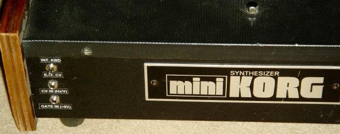
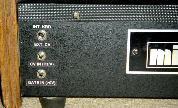
| Part 4: MOUNTING | |||||||||||||||||||||||||||||||||||||||||||
|
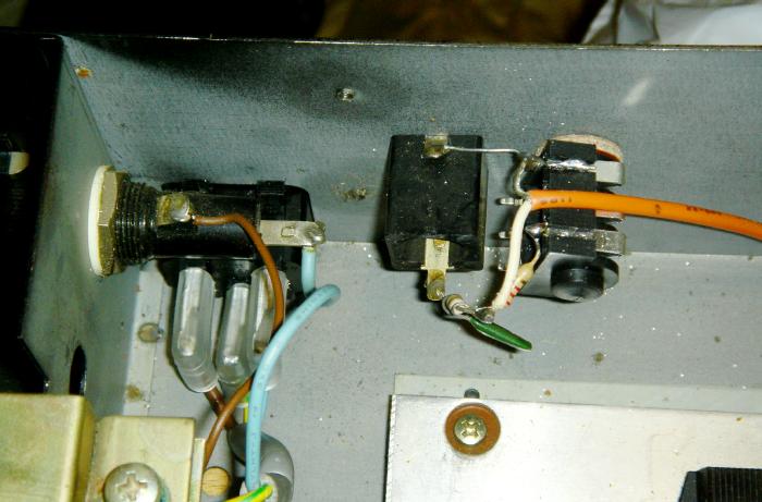
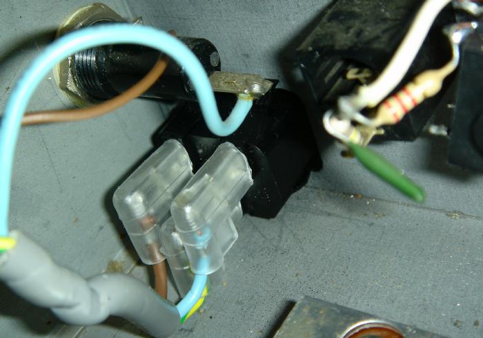
On this Mini-Korg 700S, I mounted two mini-jack sockets and the switch at the far rear right of the keyboard. |
|
||||||||||||||||||||||||||||||||||||||||||
 |
|||||||||||||||||||||||||||||||||||||||||||
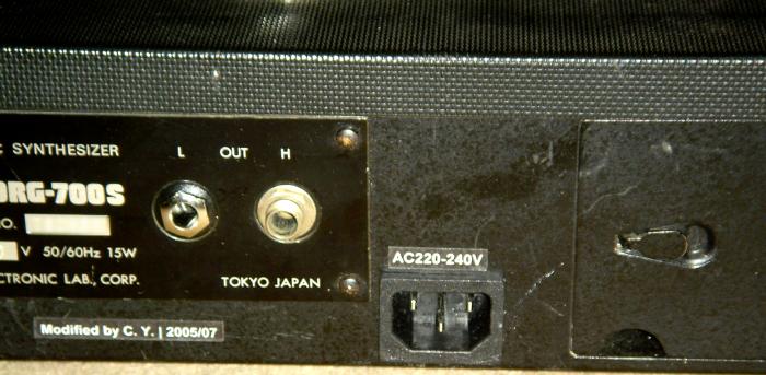
| And from outside: | |||||||||||||||||||||||||||||||||||||||||||
|
|
|||||||||||||||||||||||||||||||||||||||||||
|
|
|||||||||||||||||||||||||||||||||||||||||||
| This completes the installation guide to the Proper CV/Gate mod. | |||||||||||||||||||||||||||||||||||||||||||
| TUNING & TESTING | |||||||||||||||||||||||||||||||||||||||||||
| When first connected to External CV/Gate,
the Mini-Korg might not sound, or you get a very low oscillation. This is
probably due to the TRIMMER on the interface stripboard, not set up
properly. It needs to be turn, one way or the other, then you should start getting a wider range. |
|||||||||||||||||||||||||||||||||||||||||||
| Also, you need longer (> 1 to 2 sec) external key presses, just send external CV by holding down 1 key for a few seconds, then turn the trimmer. Once the CV/Gate gets to a suitable range, the mini-korg will trigger. | |||||||||||||||||||||||||||||||||||||||||||
| Then all you need is to tune the external CV so that the mini-korg is in tune with the outside world. | |||||||||||||||||||||||||||||||||||||||||||
![]()
![]()
![]()
![]()