|
|
Synths |
| Last Updated: | |
| Kawai S-100F - Mods | |
|
| General |
Proper CV/Gate | Filter
In CV | MIDI-fying |
Other Mods | CV Amp | | Modular Sockets | |
|
|
|
Synths |
| Last Updated: | |
| Kawai S-100F - Mods | |
|
| General |
Proper CV/Gate | Filter
In CV | MIDI-fying |
Other Mods | CV Amp | | Modular Sockets | |
|
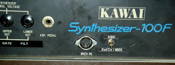
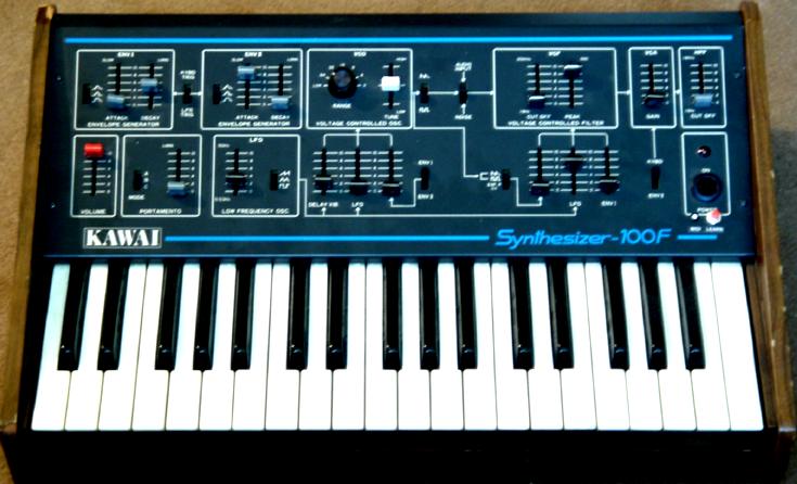
Kawai S-100F Modified with MIDI
![]()
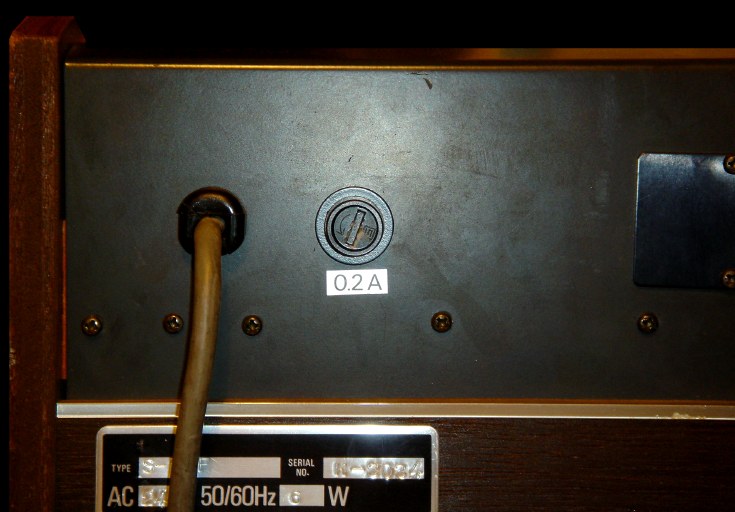
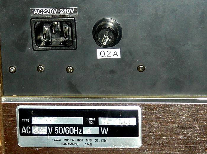
| IEC Mains Inlet Socket |
|
|
| The S-100F has a flying mains cable. This was replaced by an IEC Mains Input Socket. |
|
|
| Note: To make the IEC Mains Inlet hole, I use a screwing hand tool, which is an M10 Radius Hand Hole Cutter, 28x21mm (RS Cat.#543-614 or or 541-501), with matching 10A Snap In PCB Mount IEC 320 Plug Socket ( |
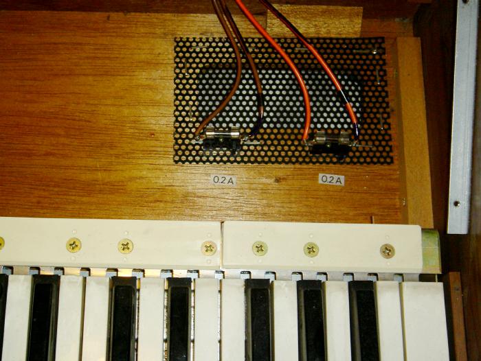
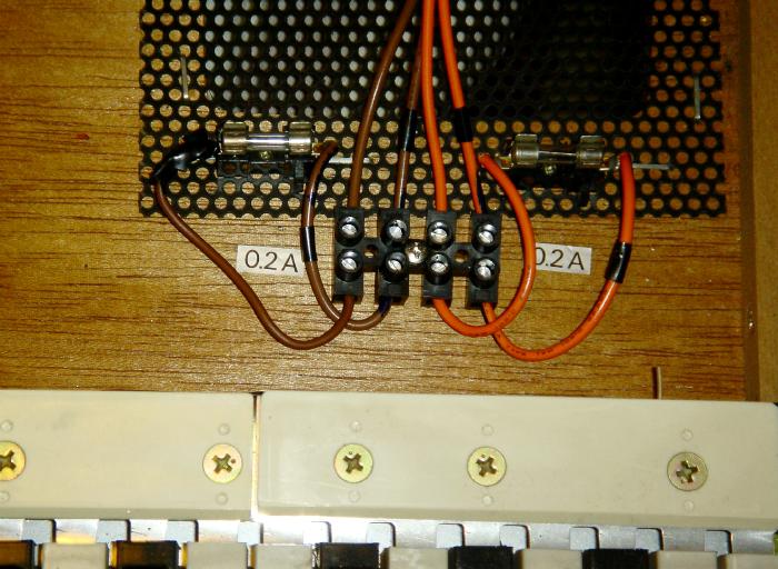
| FUSE Connections |
|
|
|
There are two mains fuses which are mounted on the wooden
cabinet. When modding, these are the only connection that kept me from separating the Front/Top panel and the wooden case/keyboard. The keyboard connection has a removal connector to the main PCB, but these 2 fuses - I had to take them out, unscrew the fuse holders and put them back when done. To simplify the process, so front/top can be easily separated/removed from the main frame, screw-in connectors were added.. |
|
|
|
|
![]()
|
The S-100F has only one CV IN socket, it is NOT a CV/Gate
Tip/Ring stereo socket. It's just CV IN, which somehow controls both CV
and GATE. CV is also in a strange +4V to -15V range, with +4V being the lowest note and -15V the highest - so, it's reversed! |
|||||||||||
|
I purchased the
Kenton socket
kit for this. It is expensive (~£77) but it does the
job perfectly. |
|||||||||||
|
|
|||||||||||
|
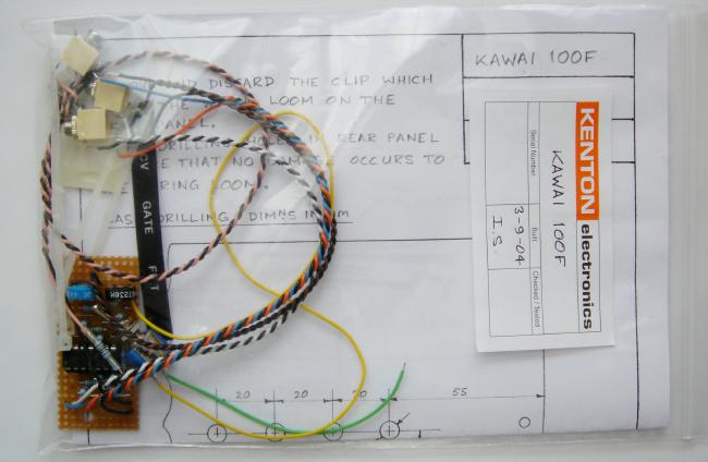
THE KENTON SOCKET KIT |
|||||||||||
|
Note: I took some notes and photos of
the board, in case anyone might like to
understand or even attempt to build a similar
board, if they find Kenton price is not appropiate. These info here are only solely for reference purposes, if you try to build this and it doesn't work, it's your own risk. Respect to Kenton!! |
|||||||||||
|
|
|||||||||||
|
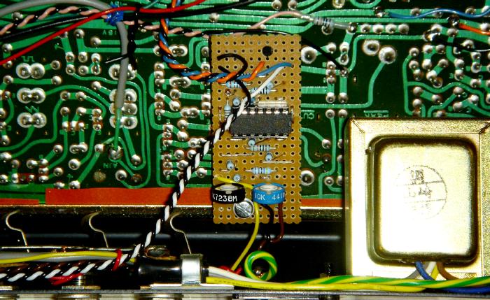
The Kenton kit contains a small stripboard, with a TL074 op-amp, some resistors, diode and 2 trimmer presets. This board ideally converts incoming 1V/Oct CV/Gate to the +4v~-15V combined CV that the S-100F needs. |
|||||||||||
|
|
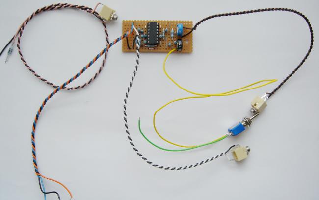
A top view photo shot of the Kenton stripboard. [Click Image to Enlarge] |
||||||||||
|
|||||||||||
|
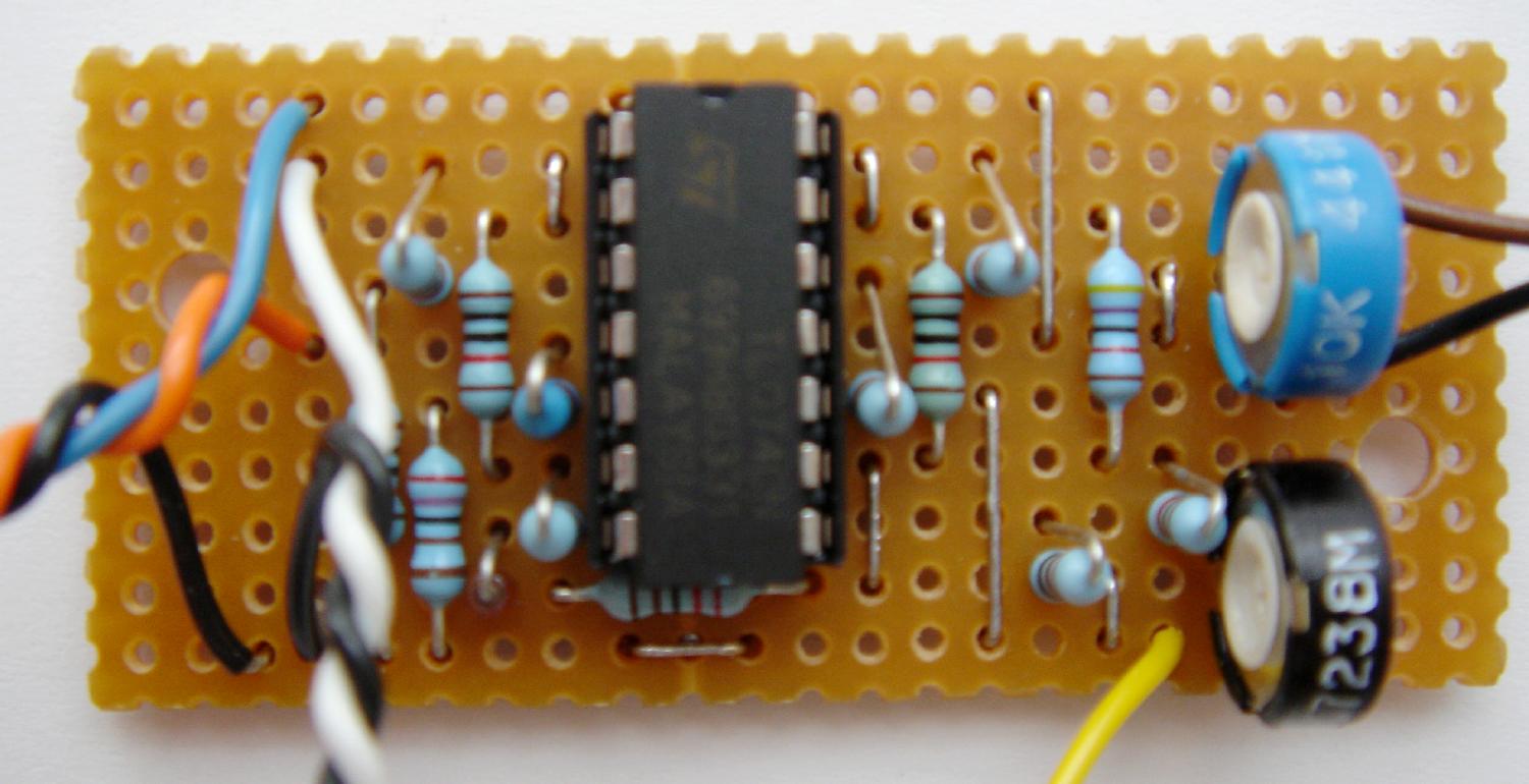
Well, I have tried to roughly work out what is what on the stripboard, in case one day anything breaks down or any wired got broken off, I have something to refer to to "service" this. |
|||||||||||
|
|
This is roughly what I've worked out. Basically a stripboard diagram of where things are on the stripboard. Tried my best to read the resistors coding, checked with multi-meter, so they should be pretty close(?)... i think all resistors are 1%. The diode I guess is a 1N4148, looks like it anyway. I won't try to build or test this, unless maybe one day when I get a 2nd S-100F! |
||||||||||
|
Power (+15V/0V/-15V) WIRING LOCATION |
|||||||||||
| For where to tapped the power, please see below, under VCF CV In, since the power location is near there. | |||||||||||
|
CV / GATE WIRING LOCATION |
|||||||||||
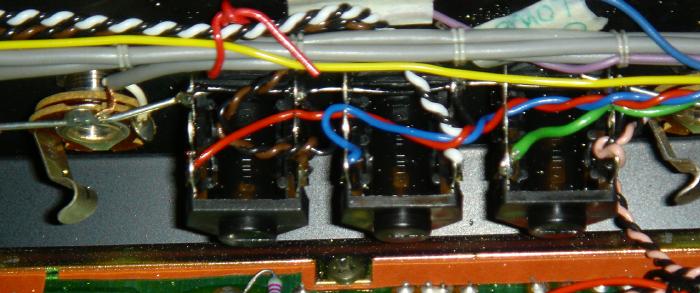
| The CV patch point is now actually the same as the CV IN Socket, which is the GREY wire located at the left of the PCB (when faced from the back - i.e. if you flip the top panel open, with sockets below the PCB) | |||||||||||
|
|
|||||||||||
| Well, facing from the other side, the red spot in the the photo below is where the CV IN is. | |||||||||||
|
|
|||||||||||
| Remove the GREY wire, and connect a wire here to the centre of an SPDT Switch. The GREY wire then goes to one side of the switch and the CV OUT from the CV-Mod-Stripboard goes to the other. | |||||||||||
| No GATE input wiring/patching is needed, since the stripboard actually converts CV/GATE to the unusual S-100F combines CV. | |||||||||||
|
Actually, the way I did this was slightly
different. |
|||||||||||
| So the easiest way is NOT to remove the GREY wire from the PCB, but remove it from the CV IN socket, connect that to an SPST switch, the other side goes to the CV OUT from the stripboard. | |||||||||||
|
The switch acts as switching between INTERNAL Keyboard CV or the EXTERNAL CV/GATE from the sockets. |
|||||||||||
![]()
|
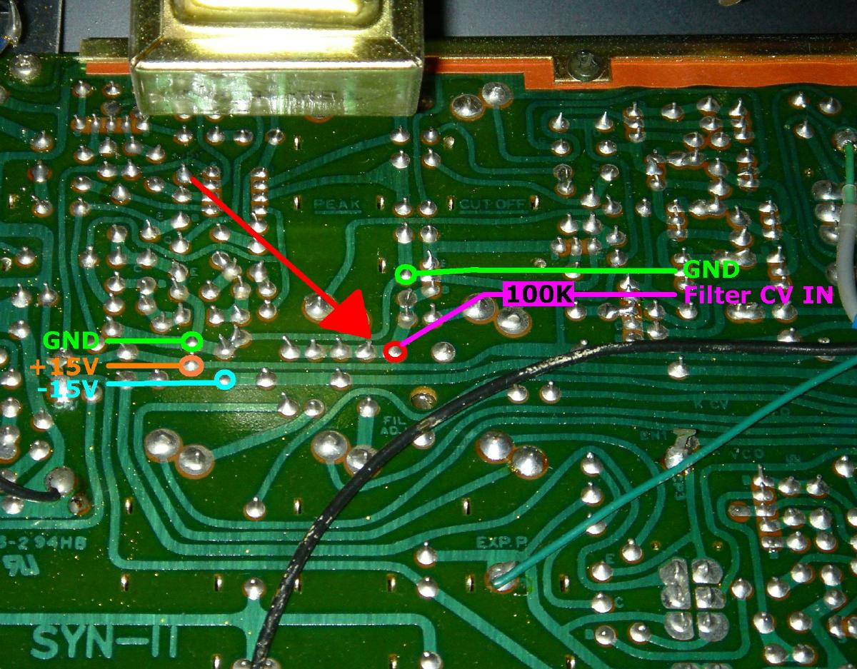
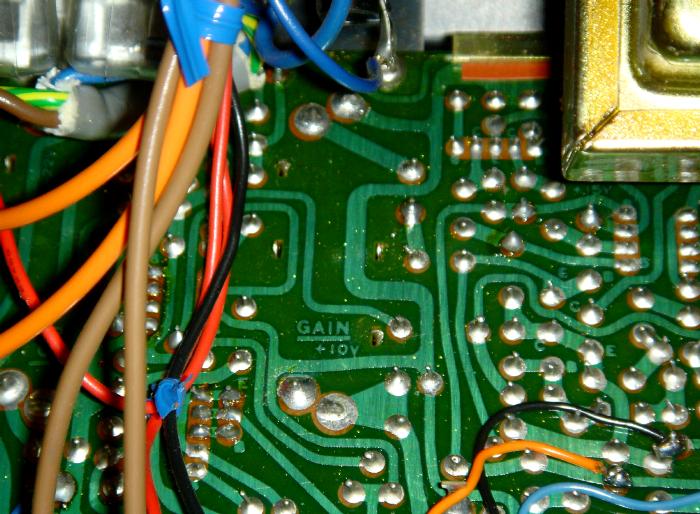
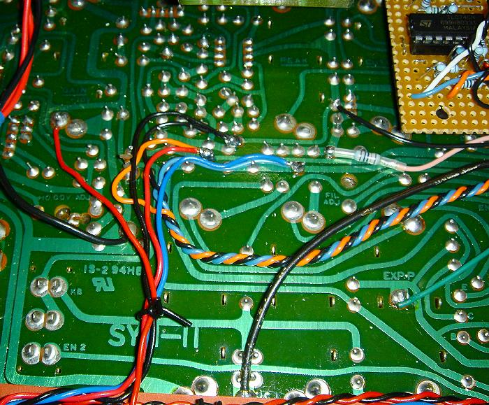
Requires a resistor (100K) and socket ... Facing from the back, we're looking at the near right of the PCB, just above the mains transformer. |
|
|
|
Facing the other way, see the red arrow below... Also, +15V/0V/-15V can be tapped here (for power for the stripboard). |
|
|
|
|
|
NOTE: The VCF Cutoff requires a CV Range of 0 ~ +15V to take benefit of the full range of the slider setting. Please see the section CV Amp below. |
![]()
|
MOUNTING |
| I mounted the stripboard on one of the screws at the bottom of the PCB, as opposed to mounting on the main cabinet as stated on the Kenton installation notes. |
|
|
|
I didn't drill 3 sockets and a switch as instructed on the
Kenton sockets manual. |
|
|
| I actually changed these to switched sockets - since I plan to add MIDI-CV |
|
|
|
|
![]()
|
Once the proper CV/Gate are dealt with, now it is possible
to add a Midi-to-CV convertor inside. Convertor needs to be able to supply 1V/Oct and +ve Gate Trigger. |
|
|
|
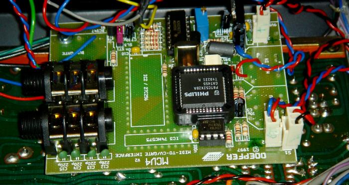
My choice for this task is again the
Doepfer MCV4.
The Doepfer MCV4 has Midi to CV/Gate (over 5 octaves range), plus 3 more CVs controlled by Midi Aftertouch, Midi Volume and a user definable Midi CC Controller. I got a couple of these, and this time they're the newer silver versions, as opposed to the older Red ones. This is actually Version2 of the MCV4. The PCB has lesser components. |
|
The MCV4 was then pre-configured - hooked up to the S-100F
sockets, then I assigned the free controller for CV4, plus, check the
tuning/pitch range. There is a small trimmer on the MCV4 PCB to adjust the pitch range of the main pitch CV out. I am actually surprised that the pitch is very very close, the Kenton board is doing a good job (obviously QC-ed/checked/calibrated before it left Kenton). So the CV out from MCV4 is only like a few cents out, and after a quick small turn on the trimmer, it is working correctly in tune. |
|
|
|
|
| So this basically is taking apart the MCV4 and wiring it inside the S-100F, but there's a little more than that. | |
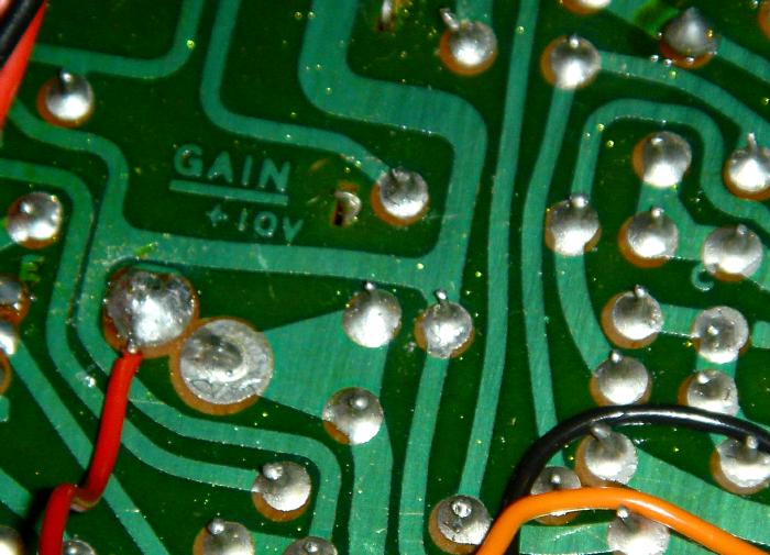
| +10V POWER | |
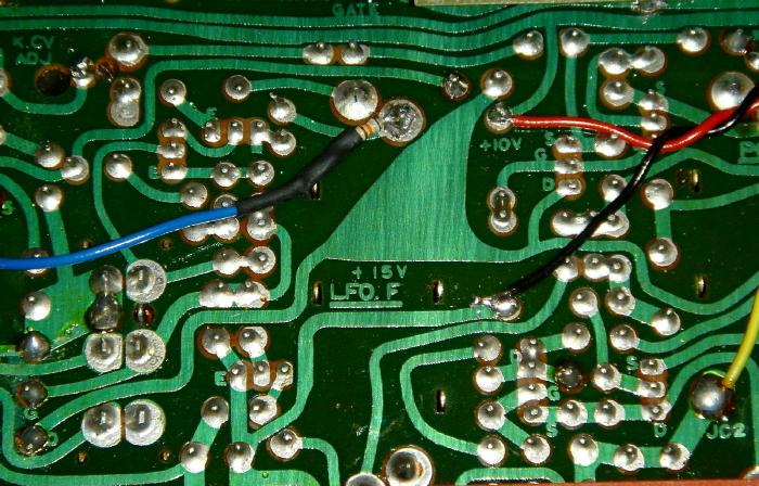
| The Doepfer MCV4 can run at anything from +9V/0V to +12V/0V - but so far the power we got from the S-100F is +15V/0V/-15V. However, the schematics confirmed that it has +10V, this could be tapped for the power for the MCV4. | |
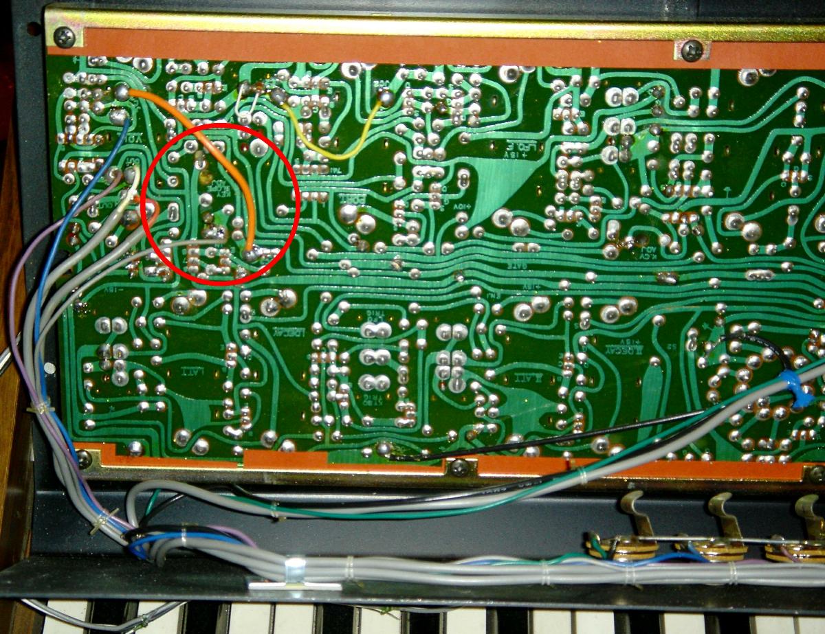
|
|
|
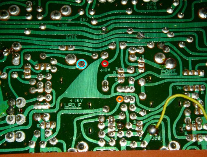
| On the PCB, just near the back of the LFO Frequency Slider, marked LFO.F, you can see the point labelled +10V (see red circle above). Thee is also a GND (0V) nearby - marked by the orange circle in the above photo. | |
|
|
|
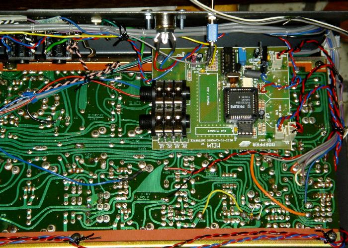
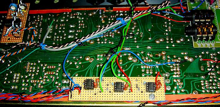
| I mounted the MCV4, just like the stripboard, over a screw (with a spacer) at the bottom of the PCB. | |
|
CV/Gate are soldered to the other ends on
the switched sockets. |
|
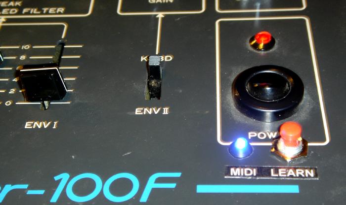
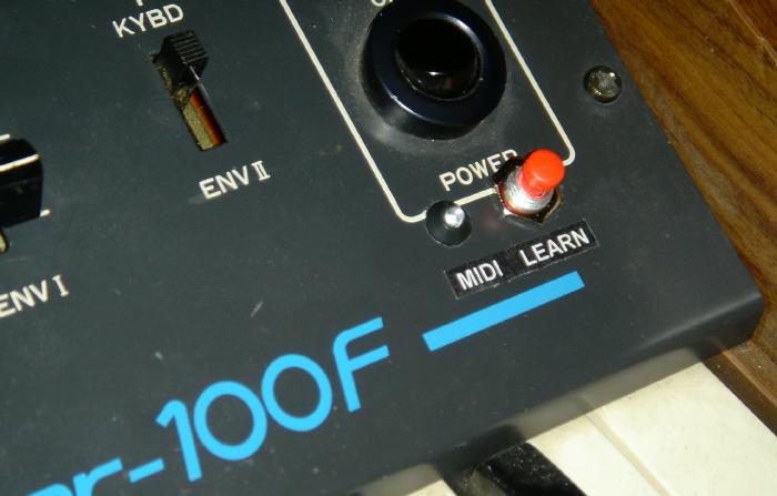
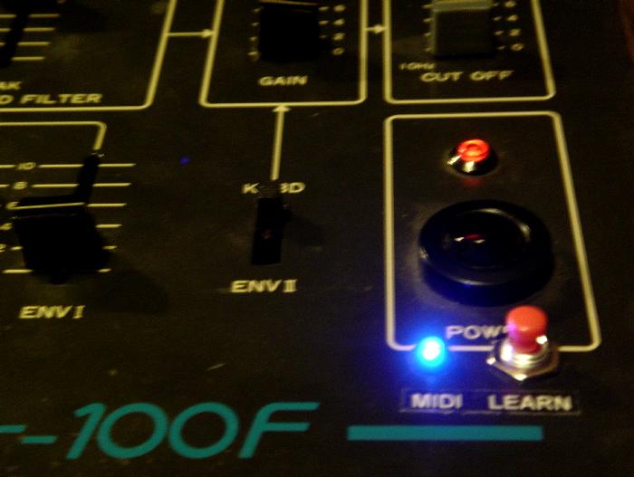
| MIDI LED & LEARN BUTTON | |
|
I drilled two holes just below the Power switch on the
front panel. Note: Cannot drill too low since it'll obstruct the top of the keyboard. |
|
|
|
|
| MIDI IN Socket | |
| MIDI IN socket is mounted at the back, where I also mounted the Internal Keyboard / External CV or Midi Switch. | |
|
|
|
![]()
| OTHER MODS | |
| There are two more CVs from the MCV4, so I thought about what I can patch these to. | |
|
I did find somewhere to use them, although
I feel that if I have the service notes, then more could be done. |
|
|
So it is more like limited guess, I suppose. |
|
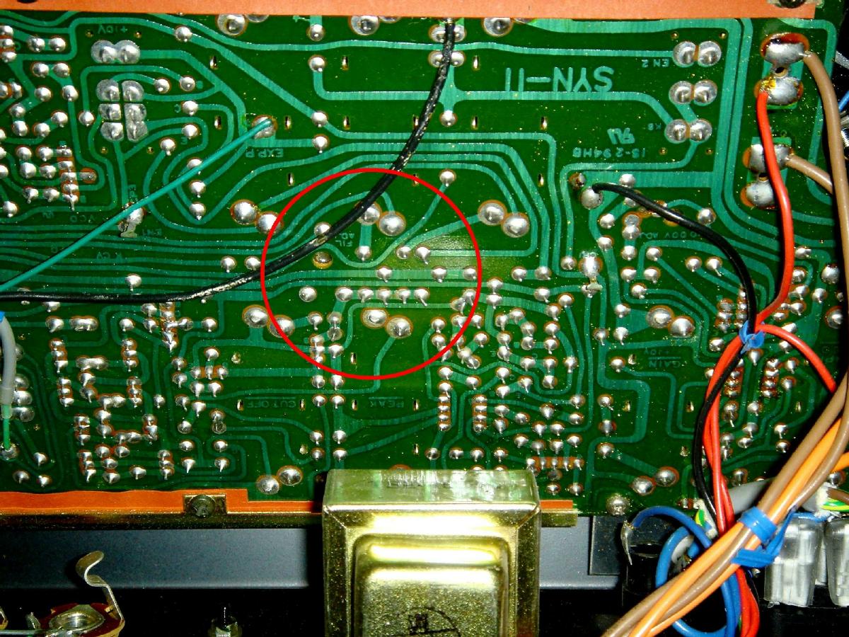
| LFO RATE (FINE TUNE) CV | |
 |
The LFO Freq/Rate Slider actually feeds +/-15V (from each
end via resistors 68K & 1K2) to the centre pole of the slider. More +ve voltages -> faster rate. So what I did was take the CV2 from the MCV4 (midi aftertouch) and wired that to a 68K resistor and then tap that to the centre of the slide. This hopefully can feed some CV to the LFO Frequency. |
| On the PCB, again, near where I've tapped the +10V from the MCV4, around where it says LFO.F, is where the slider is, as marked by the light blue circle in the photo below. | |
|
|
|
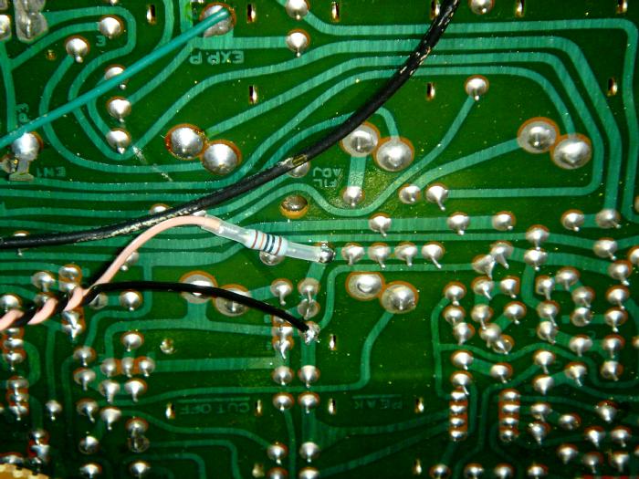
| So, a wire with 68K resistor is soldered to this: | |
|
|
|
|
NOTE: Due to the voltage range of the CV2/CV3/CV4
which gives a voltage range of 0 ~ +5V, the amount of CV giving to the LFO
Freq slider is not a lot as opposed to the +15V it uses. Additional circuit/mod can be added here to pull up the max voltage to +15V (by a simple dual op-amp gain circuit). Please see the section CV Amp below. |
|
|
|
|
| VCA GAIN CV | |
| The Doepfer MCV4 has Midi CC#7 (Midi Volume) controlling CV3 (0 ~ 5V range). | |
| I have tried tapped this to the Expression Pedal, with resistor or not, it doesn't seem to work (testing with the switch mod selected to Exp Pedal) - it doesn't seem to affect the mod slider - maybe again the voltage from the MCV4 is too low(?) | |
|
|
So I looked around for other places, and it seems the VCA
GAIN slider also takes some +ve voltages, and I decided to patch the CV to
this. A straight tap to the centre pole of the VCA GAIN slider would add voltages, no need for additional resistor. However, again, please not that it requires a +10V to benefit full slider control with the CV. |
|
|
|
|
|
|
|
NOTE: Again, due to the voltage range of the CV2/CV3/CV4 which gives a voltage range of 0 ~ +5V, the amount of CV giving to the VCA GAIN slider is only half as opposed to the +10V it uses. So this mod at the moment serves as a small / fine increase for the VCA GAIN. Additional circuit/mod can be added here to pull up the max voltage to +10V (by a simple dual op-amp gain circuit). Please see the section CV Amp below. |
|
![]()
| CV AMP | |
| The Doepfer MCV4 outputs 0 ~ +5V for its CV2, CV3 and CV4 voltages. | |
|
For the S-100F, this is not sufficient, for example, the FILTER VCF CV requires 0 ~ 10V to cover the whole range. |
|
|
So I decided to build a small simple CV Range Amplification circuit. |
|
| CV Range Amp | |
|
|
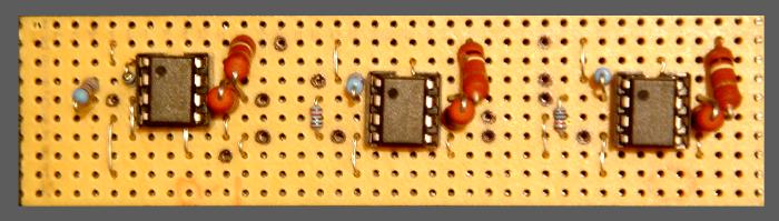
This is like basic electronics.
Simple dual Op-Amp, first Op-Amp doing the amplification The second Op-Amp then inverts it back to positive. For this task, I need two different amplifications. I needed ONE 15V and TWO 10V for the S-100F CVs. |
|
|
This is the circuit translated to a stripboard diagram. Note: |
|
|
|
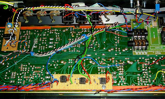
| So basically, the rest is just wiring it up and mounting again. | |
|
|
|
| I mounted the stripboard, again, on top of one of the screws, using a spacer. | |
| The power (+15V/0V/-15V) again is tapped from the same points where the Kenton board gets power from. | |
|
|
|
| Everything is then wired up, with the CV from the MCV4 going into the stripboard, and the three amplified CVs go to the LFO, Filter and the Gain. | |
|
|
|
|
So basically, now, the VCF CV works full range, even if the
slider is fully down. Same goes to the VCA Gain. Now I can have Midi Volume controlling the level of this VCA Gain, which is kinda like infinite sustain. |
|
| Just that the LFO is still a little strange. It is still a ''Fine Tune'' LFO CV. Maybe it is due to the resistor I have used. But it's good enough for me, I suppose. | |
![]()
| Other Possible Mods |
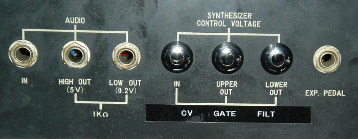
| MODULAR OUTPUT SOCKETS |
| From the schematics, there are quite a few points where signals or voltage OUTPUTS can be tapped and routed out as Modular Sockets. |
| I have not done this, but here's a list of what can be done: |
| Modular | Type | Where | ||||
|
AUDIO |
On the Waveform switch next to the VCO section, before the Ext. Audio/VCO/Noise Switch or CP3 |
||||
|
AUDIO |
On the Waveform switch next to the VCO section, before the Ext. Audio/VCO/Noise Switch |
||||
|
AUDIO |
On the Waveform switch next to the VCO section, before the Ext. Audio/VCO/Noise Switch |
||||
|
CONTROL | CP5 | ||||
|
CONTROL | On the ENV1/2 Switch next to the Mod Sliders | ||||
|
CONTROL | On the ENV1/2 Switch next to the Mod Sliders | ||||
![]()
Kawai S-100F, under Midi control!
![]()
![]()
Additional files on the Kawai S-100F CV gate Mod |
|||
|---|---|---|---|
| SOCKET KIT MANUAL PDF |
|
||
![]()
![]()
![]()
![]()
![]()