|
Noise Routing |
| This mod I got from the
elab (Japan) site. At the moment (June 2004), his site is gone and i
haven't found where it has moved to... so i'll include most details here. |
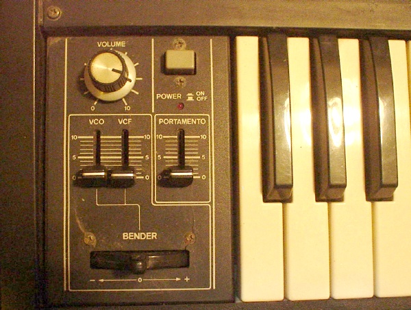
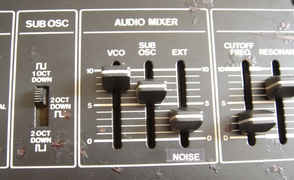
MAIN TASK:
Since the External Audio has its own Level
Fader, when not in used, we can actually route the NOISE signal to this,
thus you can have a certain amount of Noise added to the VCO Osc/Sub Osc
sound. |
|
|
|
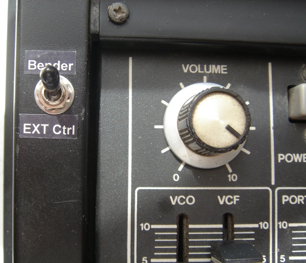
JOB:
Since the External Audio In socket is a switch socket, some PCB track
cutting has to be done. Also, we still want to use External Audio Input,
so a jack plugged into the socket would disable the Noise and have the
External Audio routed into the mixer. |
| The following diagrams were
taken from elab (Japan) site: |
|
 |
Schematics
(Click to enlarge) |
|
|
Actual WIRING that needs to be done.
NOTE:
A 10k resistor is used to attenuate to ground.
Also, a 560k resistor is used to balance the Noise signal to avoid
clipping. (Since the Audio In has a gain amplification) |
|
| |
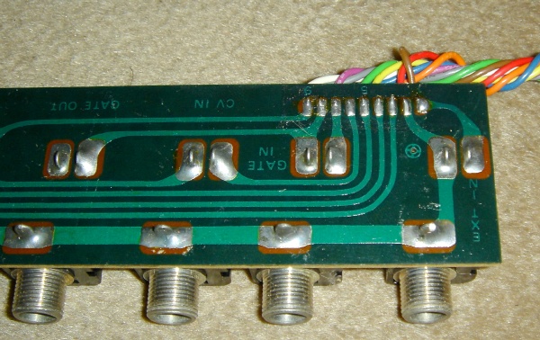
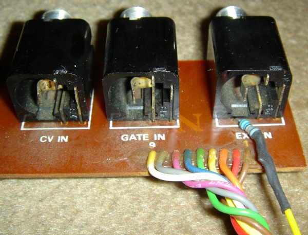
So what we need to do 1st is to
cut the PCB tracks where the Audio Input is.
First unplug the connector and then remove the screws to all the jack
sockets, the Jack Socket PCB will come out. The Audio In Socket is
the last one (on the right). |
|
|
|
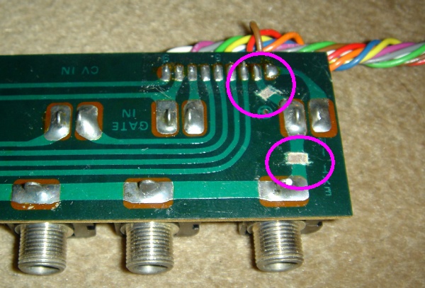
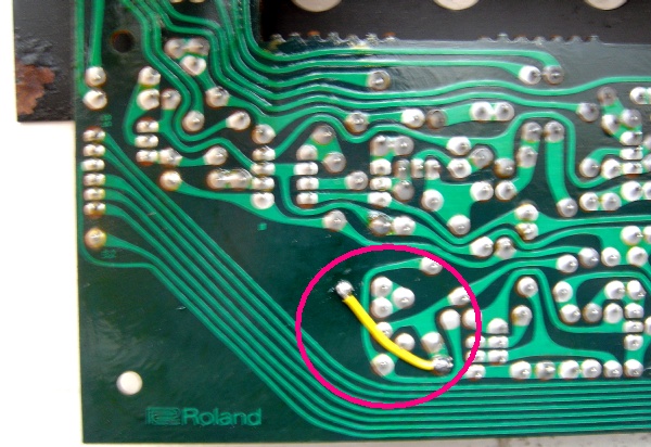
| Cut the tracks: |
|
|
|
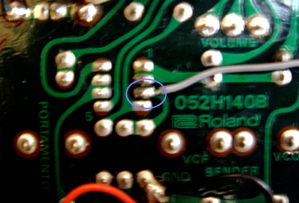
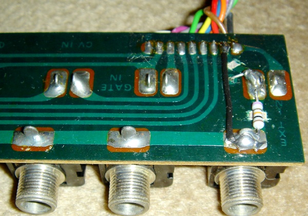
| Wire in a 10k resistor and also
the re-route ground wire: |
|
|
|
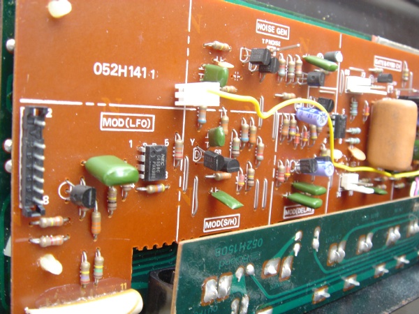
| On my SH-09, there's a little
hole there and I actually have the 560k going thru the hole 9and
soldered). |
|
|
|
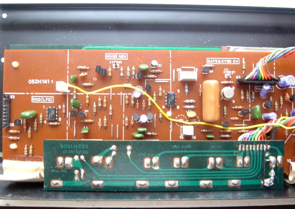
| So now the
wire will go to the NOISE output. |
| |
|
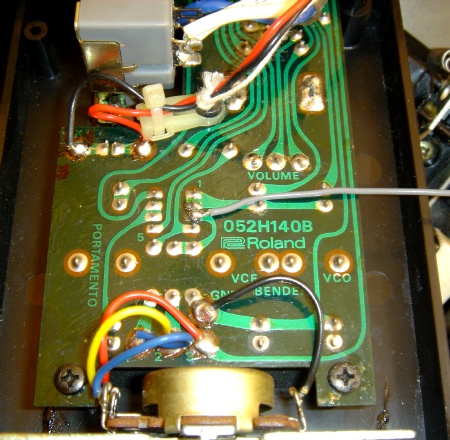
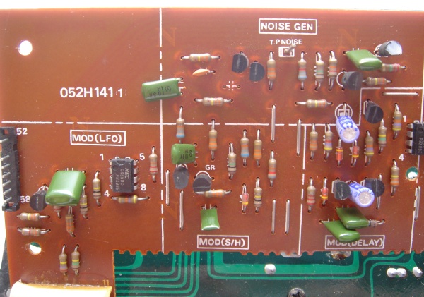
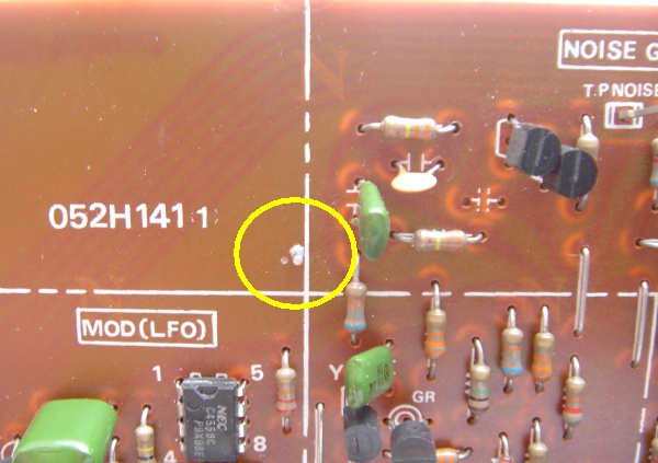
Noise Out
Location:
The Noise Gen is on the LEFT of the PCB... |
|
 |
|
| Although you can plug the wire
to the T P NOISE pin, but this Noise out is slightly Hi-Passed. the
proper Noise Out is at the leg of R173 (330k) - right leg of the top
left resistor / above C40 (100P) capacitor. |
|
 |
|
| What i did (wasn't a good move
tho)... I drilled a little hole and inserted a pin there and soldered a
short wire to the leg of R173 (330k). Well, this is so that i can just use
a header plug and plug the signal in... |
|
 |
|
| I should have fins a better
place for this, since where i am putting the plug, it will obstruct the
TRANSFORMER when the front panel is closed. (In the end I have to bend it
down a bit...) |
|
 |
|
|
But basically the Noise Re-route Mod is
done! |
|
 |
|
| So now.. without anything
plugged into the External Audio In socket, the EXT AUDIO slider works as a
NOISE BALANCE.... |
|
|
|
|
|