|
|
Synths |
| Last Updated: | |
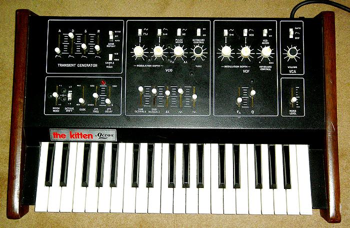
| Octave Kitten II Mods & MIDI | |
| | IEC Socket | MIDI-fying | Location/Taps | Knob Caps | Other Possible Mods | | |
|
|
Synths |
| Last Updated: | |
| Octave Kitten II Mods & MIDI | |
| | IEC Socket | MIDI-fying | Location/Taps | Knob Caps | Other Possible Mods | | |

| MODs and Work on the Kitten II | ||
|
||
|
||
|
||
|
||
|
![]()
|
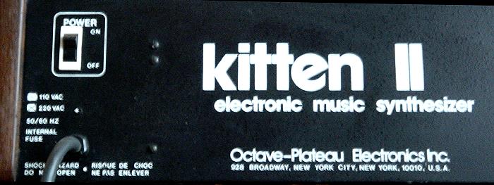
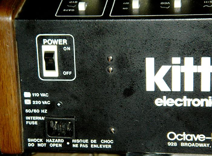
GENERAL WORKS - IEC Mains Inlet Socket |
|---|
|
I kinda don't understand - on nearly every single page on these mod pages, I have this IEC Mains Inlet Socket Mod - it seems that manufacturers have/had this obsession of flying mains leads - or maybe they really want the user to trip over the lead and drop the synth or something... |
|
|
|
The flying mains is removed, an IEC Inlet socket hole was made at the original cable outlet, then a socket is fitted. |
|
|
| Note: To make the IEC Mains Inlet hole, I use a screwing hand tool, which is an M10 Radius Hand Hole Cutter, 28x21mm (RS Cat.#543-614 or or 541-501), with matching 10A Snap In PCB Mount IEC 320 Plug Socket ( |
![]()
![]()
![]()
| MIDI-to-CV on the Kitten II | ||
|
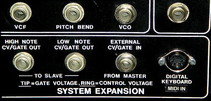
The Kitten II already comes with CV/Gate socket - on a
single STEREO jack socket - but with GATE at Tip and CV at Ring. There are tons of space inside the Kitten II, so to get it MIDI-fied, all I did was put a Midi-to-CV Convertor inside. |
||
| Choice | ||
|
|
My choice for this task is again the
Doepfer MCV4.
The Doepfer MCV4 has Midi to CV/Gate (over 5 octaves range), plus 3 more CVs controlled by Midi Aftertouch, Midi Volume and a user definable Midi CC Controller. I got a couple of these, and this time they're the newer silver versions, as opposed to the older Red ones. This is actually Version2 of the MCV4. The PCB has lesser components. |
|
|
The MCV4 was then pre-configured - there is a small trimmer on the MCV4 PCB to adjust the pitch range of the
main pitch CV out. Then it was hooked up to the Kitten II CV/Gate Socket, then I assigned the free controller for CV4, plus, check the tuning/pitch range. |
||
|
||
| Powering | ||
|
The Doepfer MCV4 can run at anything from +9V/0V to +12V/0V - but the Kitten II runs at +15V/0V/-15V. So I just built a small step-down stripboard, using 7812 to give it a +12V. NOTE: I think there is +12V on the Kitten II, but as I don't have the schematics, I am not 100% sure. So I rather do this to have the 12V where I know it is correct. |
||
|
|
|
The very simple stripboard. In fact, it could have been done without the stripboard, just wiring 7812 or 78L12 to the power cable.
|
| To be honest, this is like
real, real basic electronics. But I am keeping the info here for
reference and for anyone who might need it. Afterall, this is what I have done on the Kitten II. |
||
|
|
||
|
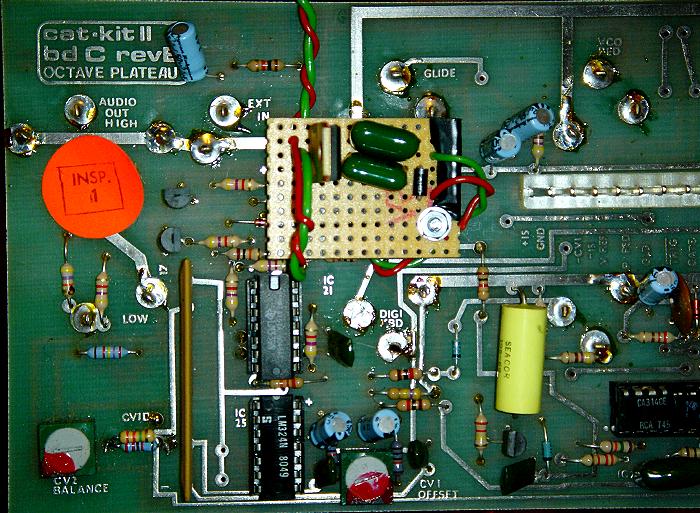
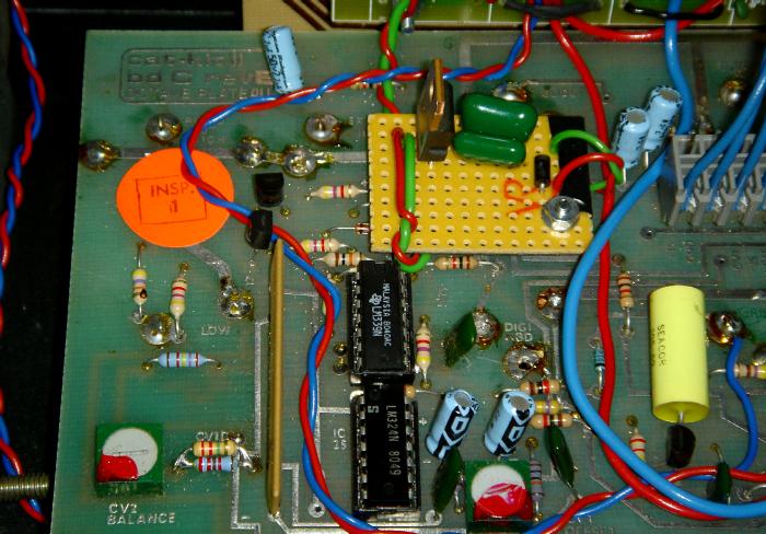
I mounted this little stripboard on the
Board C of the Kitten II. |
||
|
|
||
|
||
| Preparations - Panel Drilling | ||
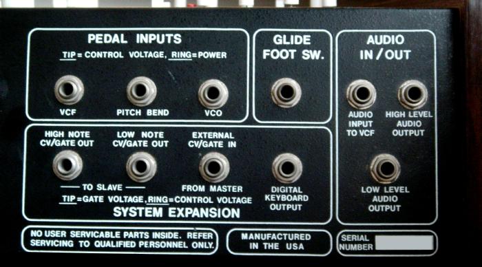
| So I needed a hole for the MIDI IN Socket, and then I needed MIDI LED and MIDI Learn Switch hole, possible on the front panel. | ||
| There is this DIGITAL KEYBOARD OUTPUT jack socket at the rear panel, that I don't think I'd ever need... | ||
|
|
||
| So I desoldered that socket - and made a larger hole there to house my MIDI IN Socket... | ||
|
|
||
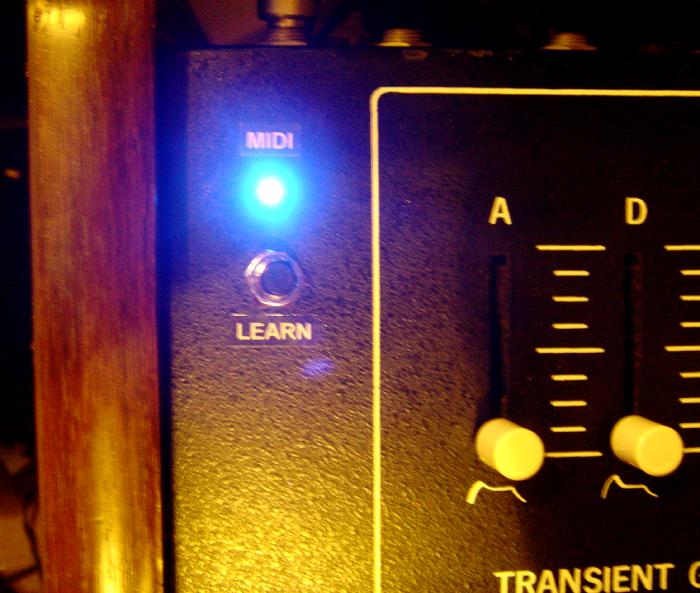
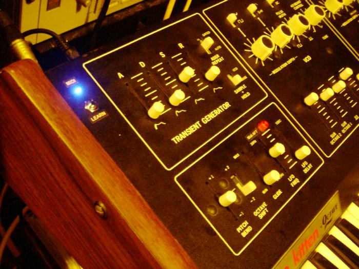
| For the MIDI LED and LEARN Switch, I drilled two small holes near the top left on the front panel. | ||
|
|
||
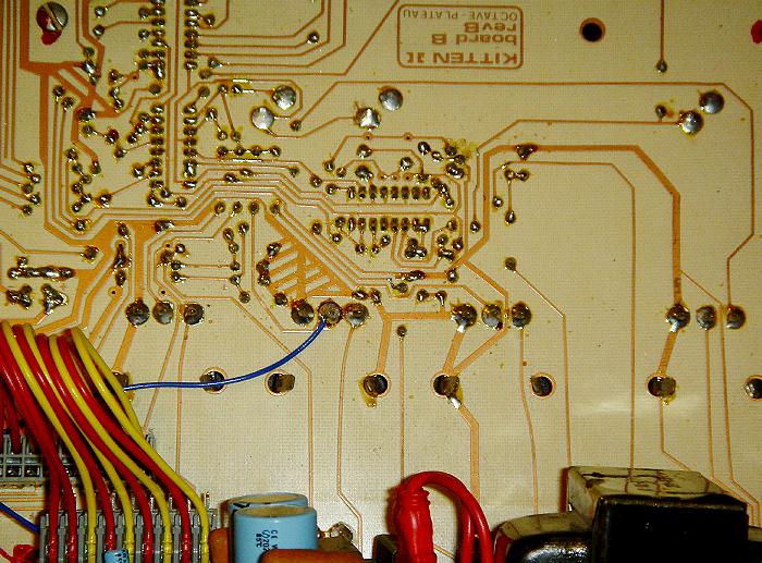
| A hole wass also drilled on the free space on Board B, where the MCV4 was to be mounted. | ||
|
||
| Mounting | ||
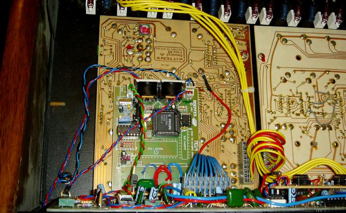
| Here's how it looks like when the MCV4 is mounted... | ||
|
|
||
![]()
![]()
![]()
| Right, looks kinda easy but those mounting did take a little time to do. | |||||||||
| After the mounting was done, it was time to wire the CV/Gate and the 3 controllers to whatever locations I wanted them. This was actually quite tricky! | |||||||||
|
| CV/Gate | LFO Fine | VCF Fc | VCF Env Mod | |
|||||||||
| CV / GATE | |||||||||
|
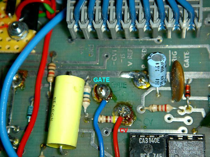
I soldered the CV/Gate out from the MCV4 to the back of the
CV/Gate socket on the PCB Board C. This acts like plugging in an external jack to that socket and feeding it CV/Gate. However, the CV/Gate In socket is NOT a switched socket. So... |
|||||||||
|
|||||||||
| But, without any schematics, I didn't want to go into looking for the CV/Gate and doing a switch just for this. So it was a straight tap to the back of the socket kind of job. | |||||||||
|
|
|||||||||
| Remember, it's reversed - TIP = GATE, RING = CV. | |||||||||
|
|||||||||
| SO I have 3 more controllers to play with, which are the MIDI Aftertouch (MCV4 CV2), MIDI Volume (MCV4 CV3) and a freely assignable Midi CC (MCV4 CV4). | |||||||||
| LFO RATE Tune | |||||||||
| I decided to wire CV2 (Midi Aftertouch) from the MCV4 to the LFO slider - without any schematics, i had to look at the PCB Board B for a long time, to see if this can work or not. | |||||||||
| After some experiment / trail & error, I think I can patch the CV2 (with say a 47k resistor) to the centre pole of the slider. | |||||||||
|
|
|||||||||
| In the above photo, you can see that red wire with a resistor in heatshrink - that's the one. | |||||||||
|
NOTE: When CV is fed to this point of the LFO slider, it actually SLOWS DOWN the LFO rate. So basically what I usually do is to set a relative speed for the LFO, then use this MIDI Aftertouch CV to slow it down or fine-tune it to my Midi tempo. It's not perfect, but what the heck! |
|||||||||
|
|||||||||
| VCF CutOff (Fc) | |||||||||
|
VCF Cutoff CV... is a ''must'' - usually I use the CV4
(freely assignable Midi CC#) on the MCV4 to do this. Well... freely assignable Midi CC# is usually assigned to Midi CC#1 (Modulation) !! |
|||||||||
| VCF Cutoff CV (location) is easy - because hey, there is the VCF CV IN Pedal Socket... | |||||||||
|
|
|||||||||
| In deed, the location is easy - it's just the back of the socket on the PCB Board C, where the TIP is the CV. But life's not so easy... in a way, I knew this was gonna happen... | |||||||||
| ISSUE: Control Voltage range. | |||||||||
|
This also applied to my Kawai
S-100F,
where I felt that the Aux CV didn't cover enough range. On the Doepfer MCV4, the CV2, CV3, CV4 outputs are 0 ~ +5V. Note: This isn't necessarily just the Doepfer MCV4s. Other Midi-to-CV Convertors have Aux CV ranges from 0 ~ +9V or 0 ~ +10V. |
|||||||||
| So initially when I tapped this 0~+5V CV4 to the Filter pedal in, it only had like 1/3 of the full slider effect. Simple isn't it, the Kitten II, running at +/-15V, requires this Fc CV to be 0 ~ +15V. | |||||||||
| CV BOOSTER | |||||||||
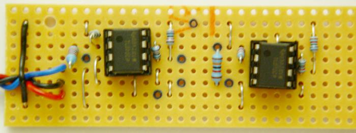
| So I decided to build a simple Op-Amp amplifier circuit for this task. In fact, I build a dual one, cos I wasn't sure if I need another amplification for the remaining Aux CVs. | |||||||||
| Schematics is simple: Op-Amp with a negative x3 GAIN then invert it back to positive... | |||||||||
|
|
|||||||||
| I picked 13K / 39K resistors because these are ones that I just happen to have and one is 3x value of the other, since I am looking for tuning 0 ~ +5V to 0 ~ +15V. | |||||||||
|
|
I did this on a stripboard.
In fact, I did a ''dual one'' - so I can amplify / boost
TWO Aux CVs if I wanted.
|
||||||||
|
This is how it looks like when built...
To be honest, this is like real, real basic
electronics. But i am keeping the info here for reference and for
anyone who might need it. |
|
||||||||
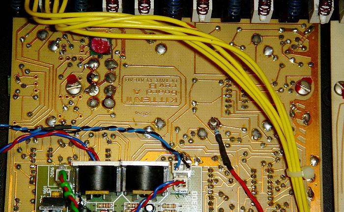
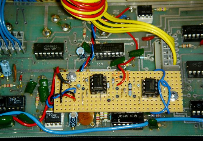
| So we need +15V/0V/-15V power for this board, and it just so happens that they are around / near the VCF Pedal Input socket on the PCB Board C. | |||||||||
|
|
|||||||||
| I mounted the board just slightly below that, again, drilling two small mounting holes in any free space on the PCB, without obstructing or cutting any PCB tracks. | |||||||||
|
|
|||||||||
|
|||||||||
| VCF ENV Mod CV | |||||||||
| So I have one more CV left, CV3 on the MCV4 (which is Midi Volume CC#7). | |||||||||
|
I had many thoughts of where I should patch this to. But without any schematics, again, it's gonna be trial and error. |
|||||||||
|
There was one particular place, being the VCF ENV/VCO Modulation Pot, that I really would like to control over CV. Because, as opposed to the Fc VCF Cutoff, which gives full control over the Cutoff frequency, this pot gives you the filter, under the ADSR (or VCO) influence. |
|||||||||
|
I tried and experiment with a few taps, I
knew it's soldering the CV to the centre pole of the VCF ENV/VCO Mod Pot
on the PCB Board B (the one in the middle on that VCF box on the front
panel). |
|||||||||
|
|
|||||||||
|
|
|||||||||
|
NOTE: |
|||||||||
| So, basically the MIDI Part is done... | |||||||||
![]()
![]()
![]()
|
KNOBS CAPS |
|
|
I thought I should mention this. My Kitten II came with some knobs without any caps. There were only 8 knobs for the Pots, only 2 of them had the Black coating caps on top when it came to me. |
|
|
|
|
| For the remaining 6 knobs, actually I tried the easiest method of painting them black, with a felt tip marker pen! But it has some old dead glue there which doesn't look right, plus the marker won't ''black'' those areas. | |
|
In the end, I decided to use BLACK PVC INSULATING TAPE -
you know, those PVC tapes are used to tape mains and electrical stuff.
These were used to cover the top of the knob, then I used a circular cutter (a compass cutter, which can cut circles) to cut out the tape, so it leaves a black circle on the knob tops. |
|
|
|
NOTE:
This is the tool I used. It's like a Compass, but
instead of a pen/pencil it has a cutter blade on the outside. I got this from
Maplins. Only
£2.99. |
| So how do they look now.... | |
|
|
|
| Well, you can see, the first 3 are insulating tape, the last one is original. Looks all right, not perfect, but what the heck, it's still better than nothing/without, cos they were like a mess of dried out glue before... | |
![]()
![]()
![]()
|
MIDI Kitten II |
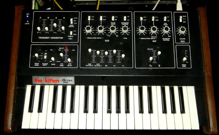
| Well, after putting everything back together, and checking everything works, my MIDI Kitten II is done!! |
|
|
| Actually I am quite delighted about it, although the size of this kitty is too big to my taste! |
|
|
![]()
![]()
![]()
|
I do have strong feelings that the Kitten II is 1/2 of the
Cat SRM 1. Or at least it's very similar. If so, there are lots more stuff that could be done, by looking at the Cat SRM1 schematics. |
|||
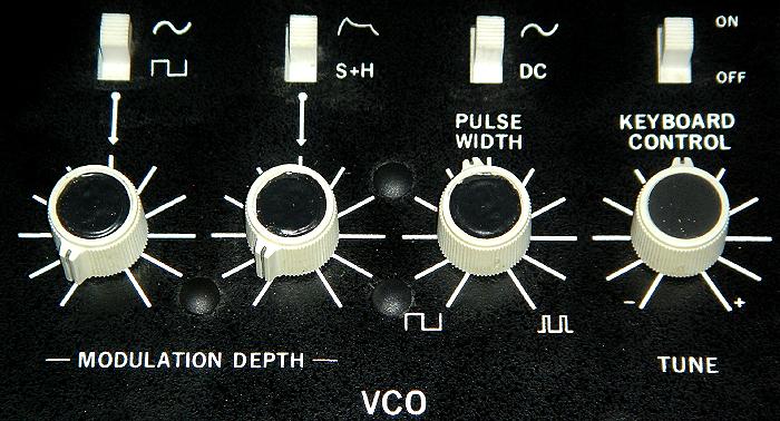
| MODULAR SOCKETS | |||
|
Even tho, without the schematics, I think
MODULAR Sockets can be patched to the switches and sliders to provide
MODULAR OUTPUTS (or Inputs). |
|||
| Possible MODULAR OUTPUTS (AUDIO): | |||
|
From VCO Mixer Slider | ||
|
From VCO Mixer Slider | ||
|
From VCO Mixer Slider | ||
|
From VCO Mixer Slider | ||
|
From VCO Mixer Slider | ||
|
From Noise Level Slider | ||
| Possible MODULAR OUTPUTS (SIGNAL/CV): | |||
|
From VCO ENV/S+H Mod Switch | ||
|
From VCO ENV/S+H Mod Switch | ||
|
From VCO LFO Mod Switch | ||
|
From VCO LFO Mod Switch | ||
| AUDIO FEEDBACK | |||
| Also, there is this saying that you can route the audio output back to the input to do some feedback tricks - but I tried that, effect is not too great - so I didn't add a feedback switch (to omit the patchcord). However, a feedback switch PLUS an audio input level control (requires amplification) could be nice... | |||
![]()
![]()
"Wooooooaaaaahhhhhoooooowwww!"
![]()
![]()
![]()
![]()
![]()
![]()