Synths
Last Updated:
KORG MS-20 (Midi-fied)
MODS - Adding MIDI CLOCK SYNC

| Home | Synth Index | Korg MS-20 | MS-20 Mods1 | MS-20 Mods2 | MS-20 MIDI | MS-20 Midi Clock |

| Choice | S-Trig Pulse Problem | Clock Processor | Mounting | ThoughtsIn Action |

Internal Midi-to-Clock SYNC inside the Korg MS-20

Midi-to-Clock Sync Converter

Task:

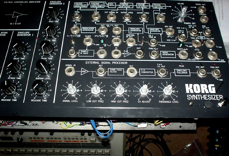
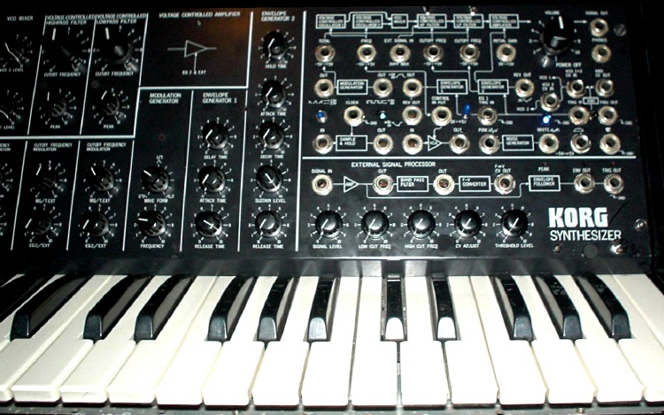
i wanted to install a small midi-to-clock sync converter inside my MS-20 so that the CLOCK driving the S&H is sync-able to Midi Clock.
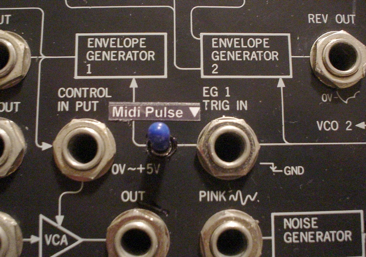
There are many things you can do with the S&H, like patching the PINK NOISE to the S&H IN, and OUT to TOTAL IN, so you get either S&H pitch or you can get S&H FILTERS on the HPF & LPF.

Available Choices?
There are quite a few Midi-to-DIN sync boxes out there. i actually got a Doepfer MSY-2 (cheap, from Vemia auctions) which also has a JACK pulse output, but somehow this doesn't work with the CLOCK IN :(

There are rough schematics on the The Old Korg Owner's Club mod page that can convert DIN sync on a Korg KMS-30 to Trigger Outs with divisions that might be usable. but i wasn't sure if this would work, since I know the Doepfer doesn't. 

There's also another Synth DIY site (Papareil Synth Labs) that has a circuit which uses a PIC microprocessor to do Midi Clock to Korg SQ-10 Sync - but it states that the pulse is not suitable to drive MS-10/MS-20, it needs to use another socket on the SQ-10...

Then I found that Emblab (in Canada) is selling their Midi Clock to DIN AND S-Trig Sync (KSB Sync Box) on eBay. (The same guy who sells the Midi 606 kit). He claims the S-trigger Out would work on Korg MS-series and SQ-10.

I actually emailed him as I've ordered a customized Midi-to-Trigger from him before, so i asked if he is sure that it would work for the MS-20 CLOCK IN. He confirmed it would and also could customize it for me as I required some parts a little different to what his box offered. Also i didn't need the box as I'd be mounting it inside the MS-20.

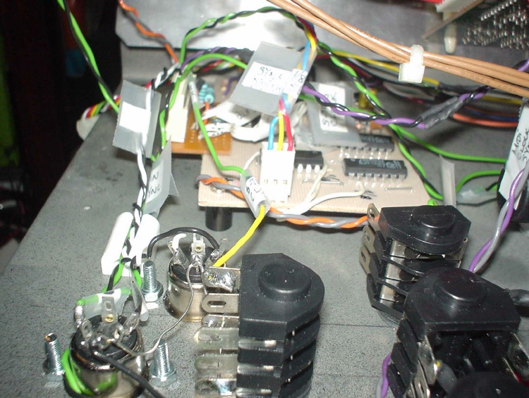
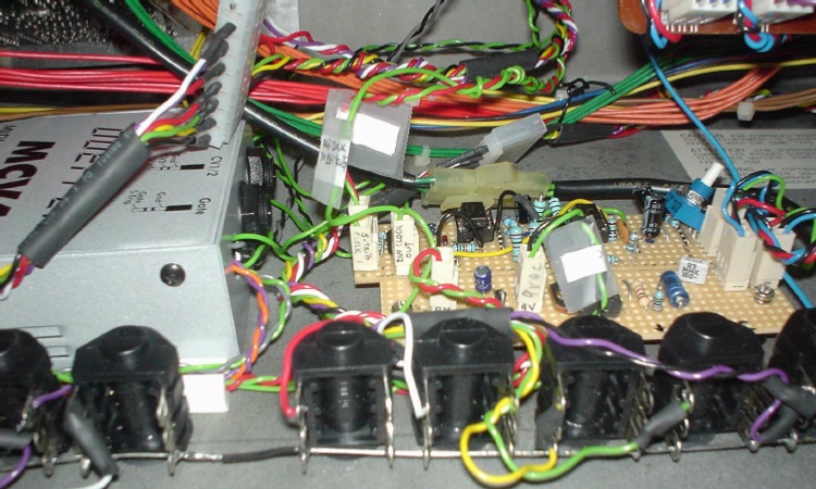
In the end, i got this board, with probably a PIC chip and a few other ICs that he has scraped off the markings so no-one could copy his PCB... it's customized to give:
- 2x S-Trigger Outs
- 1x DIN Sync instead of 3 (i dunno, i might need DIN Sync some day, a DIN Sync thru is nice!)
- 1x Midi Thru ( I ordered this before i got the Doepfer MCV-4 and as I didn't know if the MCV-4 has Thru or not, I'd rather not have 2 Midi-ins, I asked for a Midi Thru, so originally I planned the MIDI comes in to the clock converter, then Thru to MCV-4. But now, this Thru is used as a Thru to the outside world! )

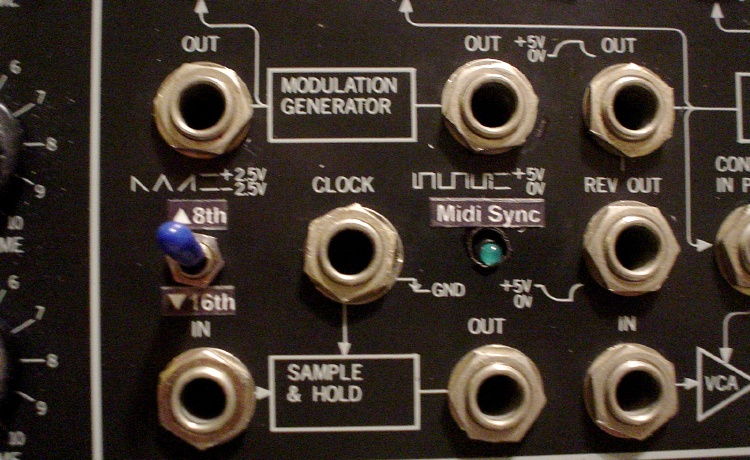
Some (limited) features of the Emblab Midi Sync:
- needs 9V supply (i can tap it from my 9V supply board inside the MS-20)
- has 8th / 16th division switch.
- no shuffle / swing / odd timing divisions tho...


S-Trigger Clock Pulse - Problem
Got the board, tried it externally on the MS-20 by plugging the S-trig Clock Out to the CLOCK IN on the front panel.
Damn, it didn't work.
Only place it would work is to patch it to the EG1 Trigger In, but that would only produce repeated FX trigger sounds, OK, maybe nice as an effect add-in, but not solving the main task.
The S-Trig pulse seems very low in volume (if I listen to it as audio signal). I emailed Emblab and he suggested i needed S-Trig pull-up, which i knew - by adding a 10K resistor to the S-Trig a one end, and to the +ve power at the other. This would pull the trigger up to PCB power voltage.

Tried it, still wouldn't trigger the CLOCK IN. This is kinda behaving like the Doepfer MSY-2... damn.

Emailed Emblab, told him the trigger pulse is possibly not long enough, he asked me to try lowering a value of a resistor by replacing it with a pot. Tried it, even with the minimum value / maximum pulse length, the MS-20 still didn't like the pulse.
 
I was dossing around with this pulse, what can I do with it? I plugged it into the ESP and see if the ESP Amplified Out would work - NO it didn't. How about the ESP Trig Out? NO it didn't.
Hmmm... what about the ESP ENV FOLLOWER Out?
YES! It works. the MS-20 CLOCK would work with an envelope followed S-Trig Clock Pulse processed by the ESP.
But... it's not nice having to patch the S-trig clock to the ESP everytime i need to use it. And there may be situations where I'd like to use the ESP at the same time while i need midi clock sync to the S&H...
Solution: i need to build the ENV FOLLOWER part of the ESP and use it as a permanent circuit to treat the S-trigger clock.
 

S-Trigger Clock Processor
I looked at the MS-20 schematics.

I needed to build the ESP, but only part of it.

The schematic scans are quite faint/blur/bad quality. So i actually re-drew the part that i needed, build a circuit and tested it, removed the parts that are not needed and some how I got a little Env Follower working...

MS-20 ESP Schematics
Korg MS-20 ESP Schematics
Click to Enlarge

This is what i ended up with:

The circuit would need +15V/0V/-15V power,


MS-20 Ext Clock Processor Schematics
Click to Enlarge

Well, I dun do custom made PCBs, so I convert everything into stripboard. It's nice, and everyone without PCB making equipment could do it. So the stripboard diagram goes:

MS-20 Ext Clock Processor Stripboard
Click to Enlarge

 
Basically after I built the circuit, i quickly tested it externally, connecting the S-trig clock from the Emblab converter, and then set the desired Trim Level. it works with a wide range so the trimmer can be left on the stripboard, set to the a working value and be left there.
Note: I think this circuit could be used as a standard Envelope Follower circuit.


Mounting
The Midi Clock Sync board is mounted above the Midi Sockets:
The Clock Env Follower Processor is mounted next to the 9V board. Power is provided by a thru connector from the -15V/0V/-15V input o the 9V board.
 
The Env Followed "Processed" Clock is connected to a switched socket i mounted at the rear panel. This socket connects to the tip of the CLOCK IN socket on the front panel.
 
Now the difficult bit...
The Midi Clock Sync board has an LED but it only indicates it's getting power, it doesn't do anything. BUT my clock processor board has a FLASHING LED, that would flash to the pulse signal :)
The Midi Clock Sync board has a division toggle switch to select either 8th or 16th.
So there's the need to mount the LED and the Switch.

Also, might as well wire an S-Trig Clock Pulse (Thru) to the EG1 TRIG for that repeating effects - but there's a need for a switch to switch this on.

It's then the painful Patch Panel removing time....
There's enough space on the left of the EG1 TRIG socket for a switch. So a hole is drilled and an SPDT switch is mounted. I had to cut a PCB trace for this switching action to work - basically, where the output from the EG1 TRIG IN socket goes to.
So the EG1 TRIG IN Socket tip goes to one end of the switch, the other end of the cut PCB goes to the centre of the switch, and the S-Trig Clock Pulse Thru (from the Clock Processor) goes to the other end of the switch.

Above the S&H In/out sockets, on the left and right of the CLOCK IN socket, there are actually 2 large holes on the inside metal patch box. These are for accessing the 2 trimmers below (but you don't see them on the front panel as they didn't put the holes there).
These seem to be the nice places for mounting the LED and the division switch. But the holes are very large. i needed something to cover it and then mount the LED and the switch.

Again, the old PC fan left over soft metal buts came in handy. I cut some square bits, drilled a hole in the middle and mounted them by the screw on the CLOCK IN socket.  Here is what it looks like:

Actually i did something more on the patch board. Since there are so many wires tapping and running out of it, i decided to mount a connector (the top left screw holds a small stripboard with the connector attached).

Well..... god this is getting complicated!


Anyway, after that i needed to drill 2 more holes on the front panel, and finally......

The Midi to Clock Pulse Trigger on EG1:

The Midi Sync to CLOCK and the Division Switch:


After Thoughts...
So basically that's it! And it took me a very long time just to get these done. Finally, at least i got it done, the way i intended to....
So many things had happened when doing this, e.g. the Midi Trig switch broke just before the final reassembly! And i didn't have an extra spare ultra miniature SPDT switch and they're out of stock in the local Maplins store - couldn't wait for online order, so i had to remove a mod switch from another synth i did - just because the space in between can only fit this particular switch size.
I used nearly half a roll of masking tape to tape up the MS-20, trying to protect it from scratch when doing the mods and the drilling. In the end i still scratched it a bit. Also, some bad measurement and the messed up LED hole etc.... Well, i have to keep reminding myself: "It's functionality that counts, not cosmetic looks" (!)
 
There are other mods as documented on the The Old Korg Owner's Club mod page, but it requires tampering with the main PCB, which needs removing all the knobs to access. Also some of the mods / schematics aren't immediately clear. I just cannot be bothered at this stage. Maybe 1 day, I will attempt them.
There's 1 drawback in this Midi-fying process  - the Doepfer MCV-4 doesn't do custom Portamento like a Kenton ProSolo. And the CV mod actually is actually after the portamento pot on the MS-20. Maybe I'll need to do some more to make portamento work, or maybe i'll investigate into the other Midi-CV converters as used in some modular synths (e.g. the Oakley/Paul Maddox PolyDAC)...
Maybe 1 day I'll learn more on Midi PIC programming and circuits, then do a better clock... there is someone who has done a Midi -> DIN with PIC that has more divisions and also it does shuffle/swing.... ah well, modding is an endless story!!!!!
 

Midi MS-20 IN ACTION!
Anyway, my Midi-fied MS-20 in action:


Home Synths

MS-20 MS-20 Mods1 MS-20 Mods2 (CV) MS-20 Mod3 (Midi) MS-20 Mod4 (Sync)