|
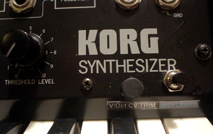
Filter External Control
Semi or Full Mod |
|
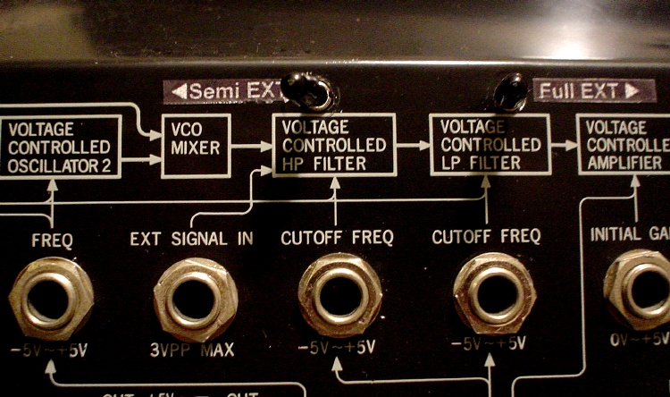
You can control the HPF and LPF with external CV. There are
tricks from MS-20 users that if you plug the jack in half way, you have
semi-external controls - i.e. the front knobs still works as well.
Initially I tapped wires to the HPF/LPF sockets and
route them to the back. This is just like inserting the jacks half-way.
But, i like to have both options - so i can choose to have HALF External
or FULL External controls of the filters. Well, I can have it by
inserting an empty jack/patchcord to the HPF/LPF socket in the front to
obtain full external control (since it's still tapped to external) but i
rather have switches.....
Sometimes, being too optimistic/idealistic could be a
pain. there's a Chinese saying that goes "if I don't walk into hell, who
would walk into hell?" meaning there's someone who would go do something
people find hard or impossible. Well, my aim for modding is to add
functions and make the synth work the way i wanted it to - so i feel i
should go thru the pain in removing the 2x35 screws.... anyway, i wanna do
midi and it'd require me to put extra stuff there, so i'd have to open it up.
|
|
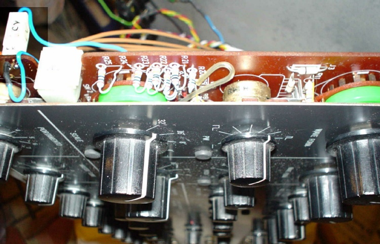
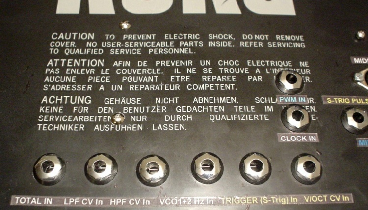
So i went thru all the way to temper with the HPF/LPF
sockets on the Patch Panel.
For this mod, i just needed to replicate the switching
action of the jack sockets.
Since i have the External tapped to the TIP of the
socket, basically it's just a matter of a SPST switch that acts like the
inserting of the jack which breaks the signal on the switching action on
the socket. |
 |
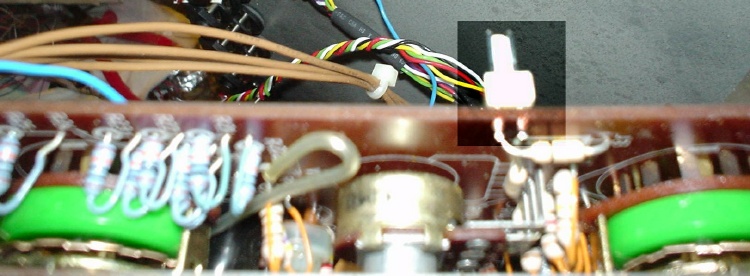
So, de-solder the jack socket, bend up (or remove) the
side-tip, so that it won't get re-inserted to the PCB. Then solder the
socket back.
2 wires that tapped to the PCB, one to the tip (where i also have the
external wire soldered to) and the other to the now blank side-tip solder
point.
These then go to an SPST switch. |
|
i just realize there could be other ways of doing this, but
what the heck...... |
|
|
|
There is just enough space on top of the patch panel for
small switches, so it's be ideal to put these 2 switches above the HPF /
LPF box drawing. BUT it might be troublesome if later i want to do
additional work on the panel box, so these switches have to be easily
removable if needed.
So instead of mounting them directly to the front panel,
i mounted them above the panel box as an extension: |
|
 |
|
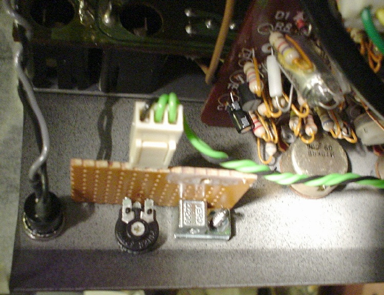
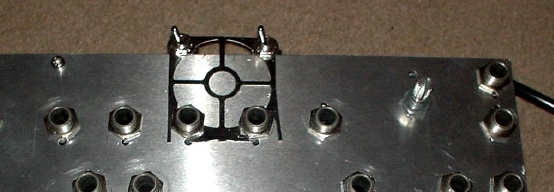
(This is very DIY!) I needed some thin metal that I can use
to support and mount the switches. It would be nice if i can mount the
metal by screwing on the jack sockets rather than extra screws. So I found
an old PC fan cooler that the fans are long not working, remove the fans
and cut out parts of the metal grid, and luckily it fitted nicely! |
|
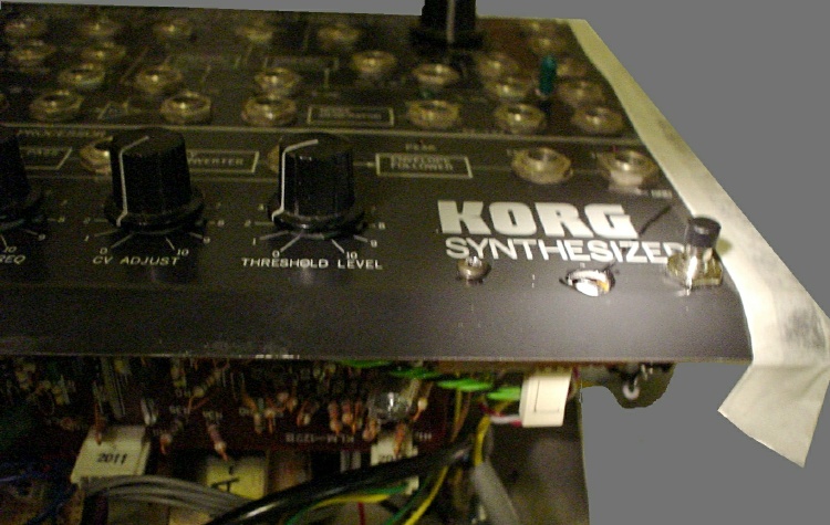
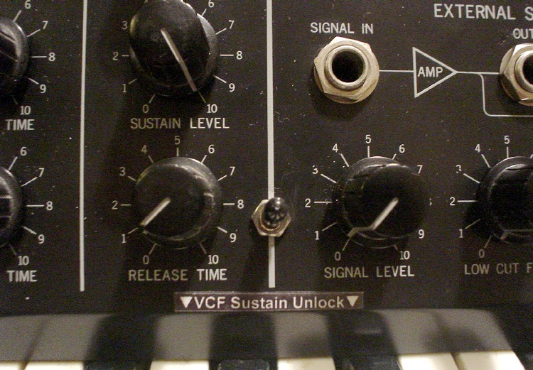
So my final Filter Semi <-> Full switches look like this:
|
|
 |
|
Semi External (Normal) to the left, and Full external to
the right. One for HPF, one for LPF. |
|
|