|
Proper External CV/Gate In |
Again, like the
800DV, the Japanese
E-Lab site has
all the info and the proper CV/Gate Mods Schematics on the Korg 700 (site in
Japanese). Since the 700S is essentially a 700 plus the Ring-mod board,
the basic CV/gate section is the same and is compatible.
[I don't fully understand Japanese, but can read certain Chinese
characters that Japanese uses and also I do know a fair amount of the
"English" characters in Japanese symbols, so I could roughly understand
the info on the site. Also, info on the schematics are given in English.]
The circuit/schematic that he provides, also
incorporates a CV Tuner, which is very useful!
E-Lab
site actually provides 2 different CV/Gate mods, one
BASIC and one
FULL which would keep all the Repeat, Bender, portamento, Vibrato
working under External CV. This was the one I headed for. |
|
UPDATE (2005/07): |
Before, I didn't put up the full details and schematics on this site
because I don't like to look as if I am stealing E-Lab Japan's great work(s),
but...
Since E-Lab (Japan) site has vanished (as from mid 2004)...
I did manage to save some of his pages for offline viewing.
So, here are the schematics diagrams for the CV/Gate Mods:
BASIC
and
FULL. |
| |
|
The Stripboard |
700S Full CV-Gate Stripboard:
Click to Enlarge |
As suggested by E-lab Japan, I used
the OP-07 op-amp instead of having to use a stepdown voltage regulator (as
the 700S operates at 20V, but most op-amps' max supply voltages are <
15V)
The circuit is again built on stripboards...
I dun do custom made PCBs, so I
convert everything into stripboard. (It's nice, and everyone without PCB
making equipment could do it.)
|
| |
| PARTS LIST (for
the FULL Mod) |
| Resistors: |
Quantity |
| 10K |
x8 |
| 100K |
x8 |
| 1M |
x1 |
|
|
| Trimmers: |
Quantity |
| 20K Trimmer |
x1 |
|
|
| I.C. / Transistors / Diodes |
Quantity |
| OP07 Op-Amp |
x2 (*see notes below) |
| 2SC1740 (or equivalent) |
x4 |
| 2SA1015 (or equivalent) |
x2 |
| 2SK30 (or equivalent N-Channel FET) |
x1 |
| 1S1588 or 1N914 Diodes |
x5 |
|
|
| Misc. |
Quantity |
| Stripboard |
x1 (at least 40x15) |
| + the usual wires,
solder, connectors etc |
|
|
| * Note: |
OP-07 is used because the
Korg 700/700S run at 20V. OP-07 is an Op-amp with the correct
rating.
It is possible to use other Op-amps, or even modify the board to use
a dual Op-amp, but the power has to be dropped down from +20V to
+15V with a 7815 or a 78L15. (see the side box in E-Lab Japan's schematic
drawings) |
| |
|
| |
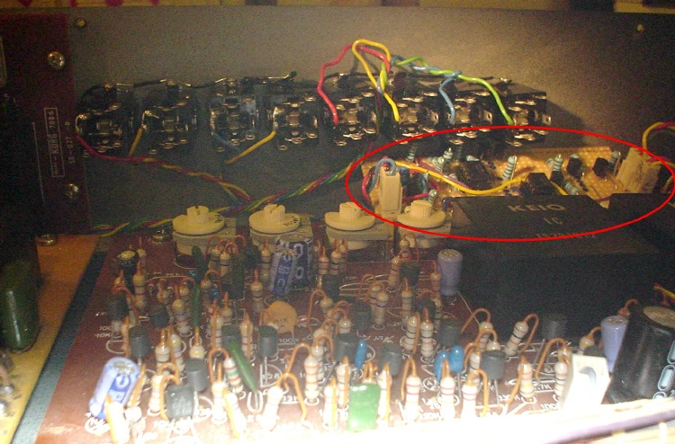
| This is roughly how
it looks like when built: |
|
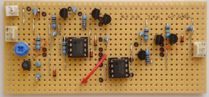
Click to Enlarge |
| |
| |
| Mounting and
Wiring |
|
 |
| |
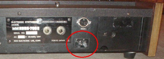
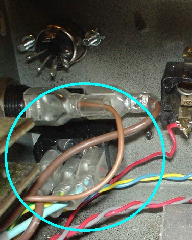
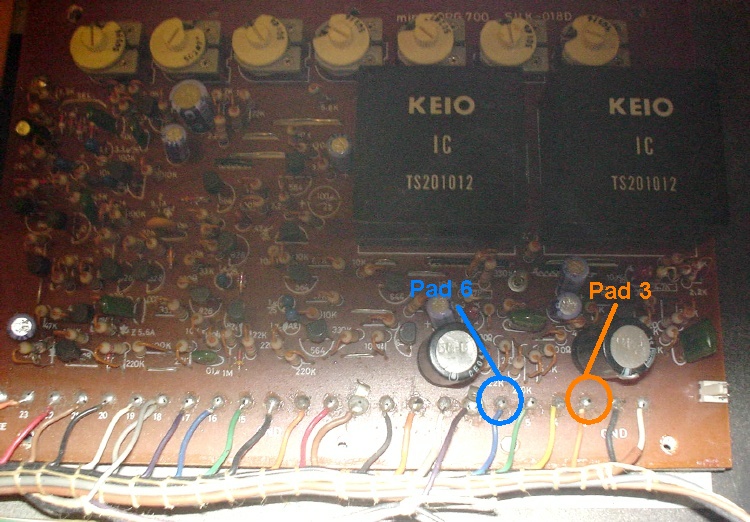
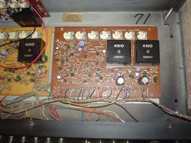
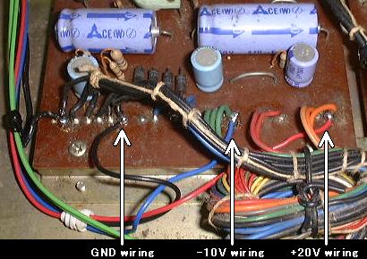
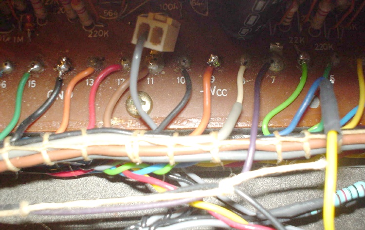
| POWER Tapping |
The +20V/GND/-10V
can be tapped from any of the 3 Korg boards (or on the 4th board on the
700S).
Basically they're on the pins on each board,
ones marked +Vcc is the +20V (usually with orange/red wire soldered to),
ones marked GND is the 0V (usually with black wire soldered to),
and the ones marked -Vee is the -10V (usually with blue wire soldered to). |
|
Easiest is to fins them on the left-most
board (the PSU board): |
|
Picture courtesy / from E-Lab Japan
|
| |
| Other Mod
Locations.... |
|
UPDATE (2005/07): |
|
Originally I didn't put up full details on where to solder the CV/Gate
mod, because I respected E-Lab Japan's work, so I put a link above to link
to his page, where all the instructions are given. (Although in Japanese,
the images are in English, and should be very helpful). |
However, after his page has vanished in mid 2004, I have a few enquiries
about the CV/Gate mod.
And in July 2005, this really cool guy called Dirk has decided to
follow my stripboard to build his CV/Gate mod.
so it's kind of my responsibility that one fully understands what's going
where, but that reference page has vanished! |
BUT WAIT! I have the offline contents saved on my harddisk.
Well, the page is basically in Japanese. I don't understand Japanese,
although I can read the Kanji (same as Chinese characters) and also I
understand the Japanese English Character Symbols (i.e. some symbols that
when put together and pronounced, it becomes an actual English word).
So I decided I'll write some notes underneath his original Japanese
paragraphs, so anyone reading them would get some idea of what it's about,
instead of just looking at the images!!! |
|
---> Full (Proper) External CV/Gate Modifications
<---
by E-lab Japan, with notes by C.Y.!!
|
| |
|
UPDATE2 (2005/07): |
Well, I have actually modded my 2nd Mini-Korg 700S with Proper CV/Gate.
This time I have taken a lot of photos and written a step by step guide,
similar to E-Lab Japan's one, but in English. Please see the
Korg 700S #2 Page. |
|
--->
Step-by-Step Proper Ext. CV/Gate Mod
<---
by C. Y., on Mini-Korg 700S #2 |
| |
| |
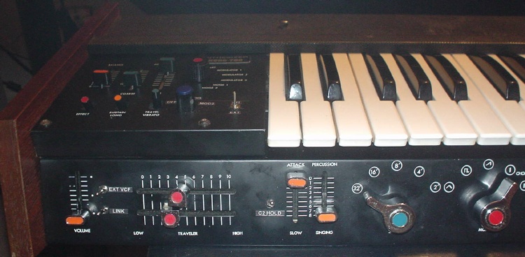
| Mounting the
Stripboard |
Loads of space
around the VCF PCB area....so i mounted the CV-Gate
stripboard above the VCF PCB.
 |
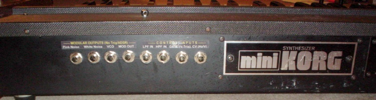
| I moved the name
plate on the rear to the centre - because the extra Ring mod board is
located vertically in the rear centre, and there's no space to mount any
sockets. By moving the plate to the centre, the area behind the VCF board
provides lots of spaces for many many sockets! |
|
 |
The REPEAT function
is tapped from Pad 11 on the VCF board:
 |
| |
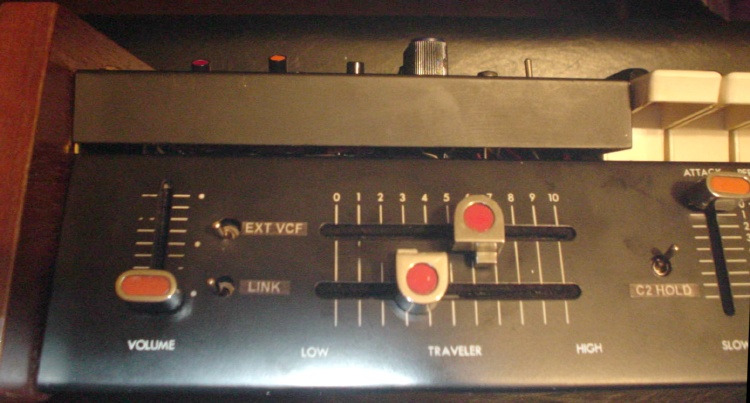
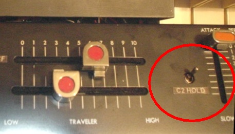
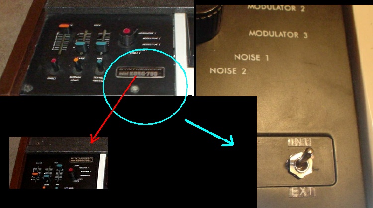
I use a small ultra
miniature DPDT switch to switch between the Internal keyboard and External
CV.
On the left panel, there's a space but was covered up by a name plate. I
removed the plate and put it somewhere above, then mounted the Int/Ext
switch there: |
|
 |
| |